Contactor vs Relay: Differences, Applications and Selection
The main difference between a contactor and a relay is the switching duty each device is designed to perform. A contactor is generally selected for repeated switching of a power load, while the term relay covers a wider family of devices used for control logic, timing, monitoring, signal switching and protection functions. They may share an electromagnetic operating principle, but they are not interchangeable based on current alone.
Contactor vs Relay: Quick Answer
- Choose by the exact function, load type, AC or DC duty, switching frequency and manufacturer ratings, not by a universal current threshold.
- Contactors typically provide main contacts intended for repeated power-load switching and may include auxiliary contacts for control or status functions.
- A control or timer relay normally handles a control task; monitoring, overload and solid-state relays are different device categories with different selection rules.
- Motor inrush, inductive duty and DC interruption can place much greater stress on contacts than a resistive load with the same nominal current.
- A contactor and relay often work together. Neither should automatically be treated as short-circuit protection.
Contactor vs Relay: Key Differences at a Glance
| Selection point | Contactor | Relay |
|---|---|---|
| Primary role | Repeated switching of a rated power load | Control, signal, timing, monitoring or another defined relay function |
| Typical circuit role | Main power switching, with optional auxiliary contacts | Usually a control or signal role, depending on relay type |
| Contacts | Main contacts designed for the specified load duty; auxiliary contacts may support control logic | Contact arrangement varies widely by control, timer, monitoring, latching or other relay type |
| Load assessment | Operational current or power, utilisation category, inrush, AC/DC duty and switching frequency | Contact rating, load type, output form, switching frequency and the relay’s defined function |
| Arc management | Construction is generally adapted to the power-switching duty stated by the manufacturer | Depends strongly on relay type and rated contact duty |
| Common uses | Motors, heating, grouped lighting, HVAC and managed loads where correctly rated | Interlocking, timing, sequencing, monitoring, signal multiplication and control logic |
| Protection | Not automatically overload or short-circuit protection | A standard switching relay is not automatically circuit protection; protective relays require separate interpretation |
The table is a functional comparison, not a substitute for a product data sheet. A high-capacity relay and a small modular contactor can overlap in apparent current rating, yet still differ in approved load duty, endurance, contact arrangement and application.
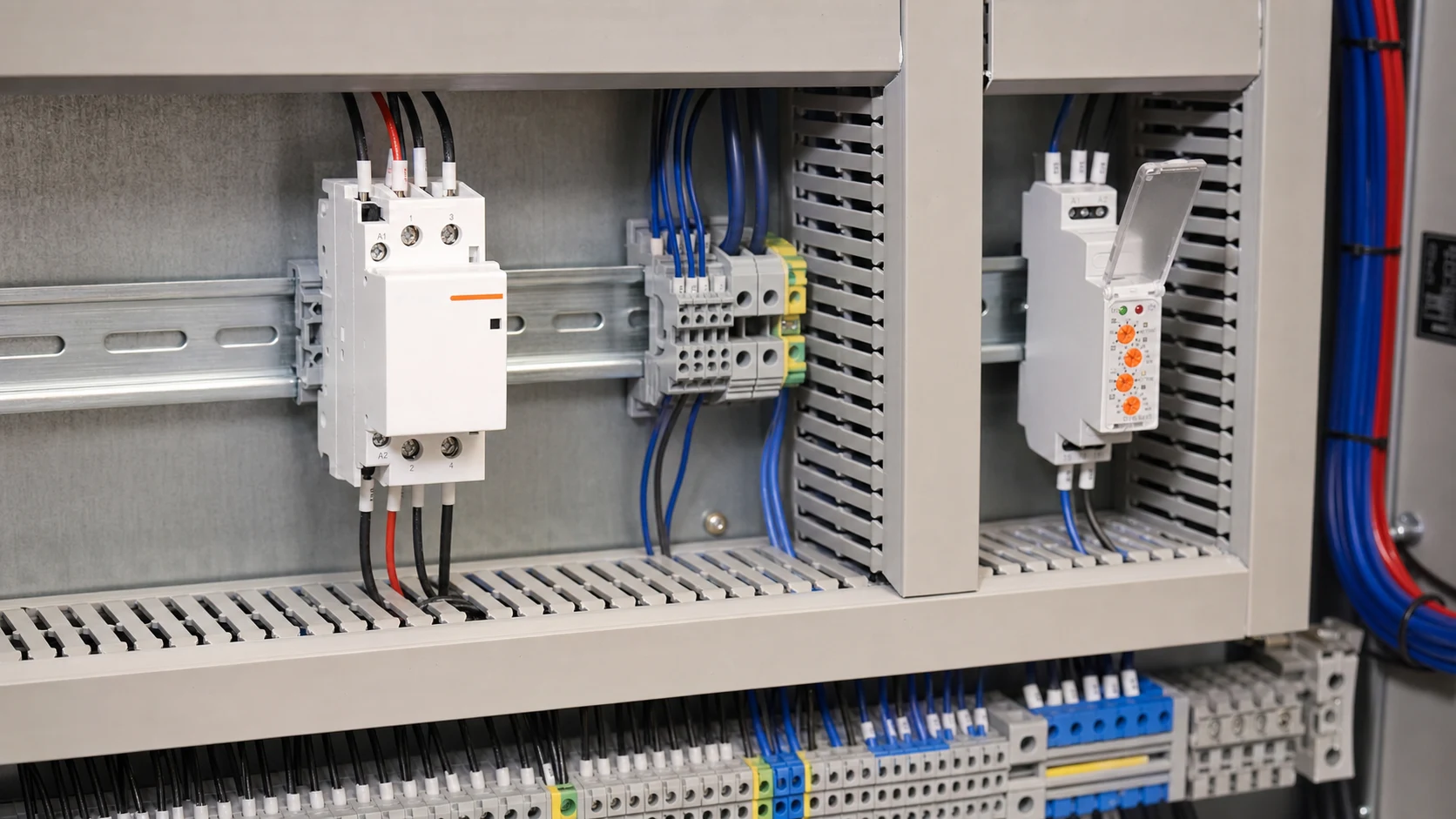
How Do Electromechanical Contactors and Relays Work?
An electromechanical contactor or relay commonly uses a coil, magnetic circuit, movable armature, spring and one or more contacts. When the coil is energised, the magnetic force moves the armature and changes the contact state. When control power is removed, the return mechanism restores the normal state unless the device uses a latching design.
This shared operating principle does not make the products equivalent. A contactor is designed around a declared switching duty for its main contacts. A relay may be designed to reproduce a control signal, add a time delay, monitor an electrical condition or perform another specialised task. Its output may be an electromechanical contact, a semiconductor output or a control signal.
A solid-state relay is an important exception to the moving-contact description. It uses semiconductor switching and has different considerations, including voltage drop, heat dissipation, leakage current and failure mode. Those characteristics should not be applied to an electromechanical relay or contactor.
Why Does Load Duty Matter More Than a Fixed Current Threshold?
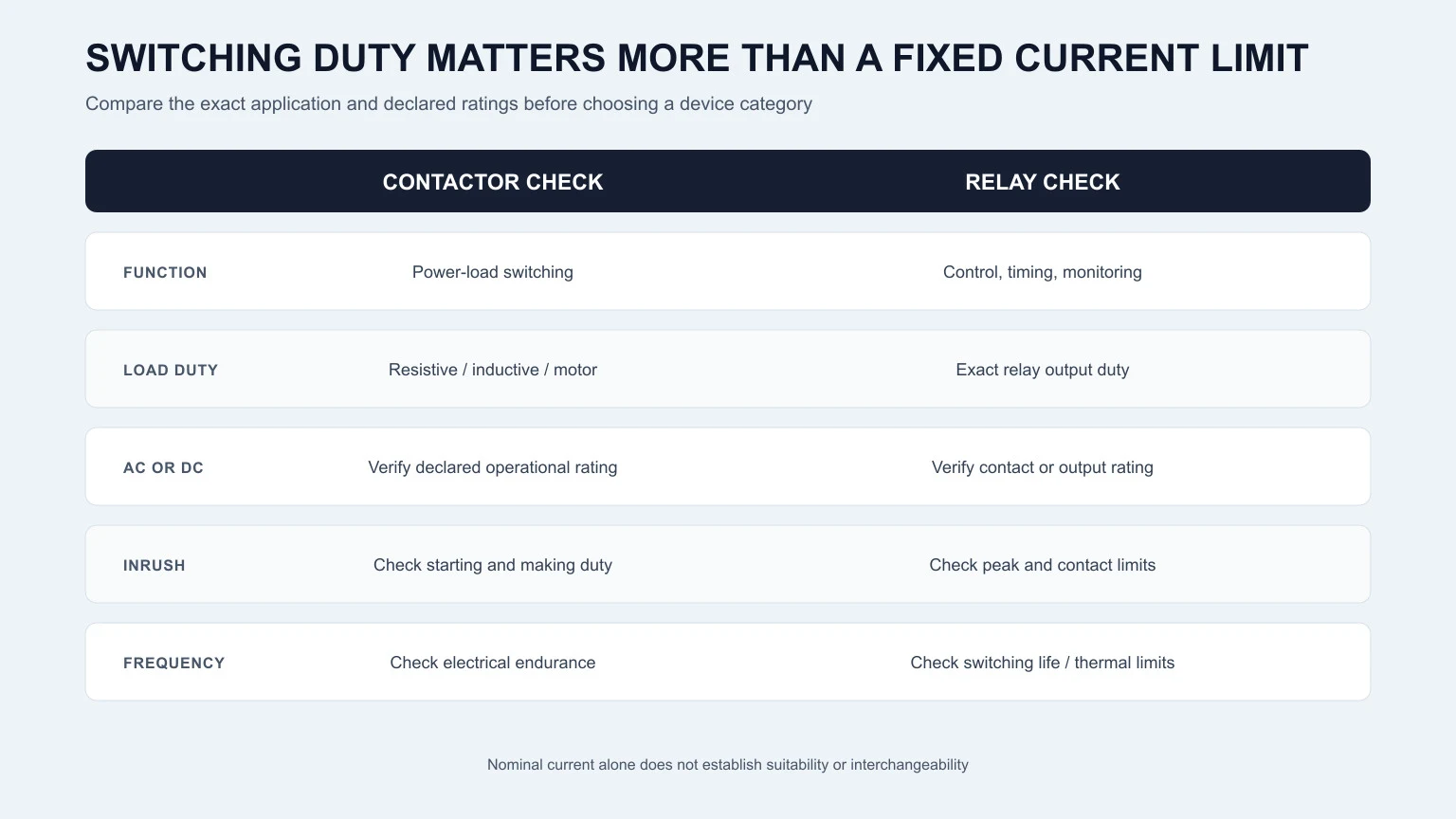
There is no reliable universal rule that a relay should be used below one current and a contactor above it. The same nominal current can represent very different switching stress depending on the load. Selection must follow the rating conditions and intended duty stated for the exact device.
Resistive and inductive loads are not equivalent
A resistive heater and an induction motor may draw the same steady-state current but behave differently when switched. A motor can impose a much higher starting current, while coils and other inductive loads can produce significant voltage stress when interrupted. The manufacturer may therefore publish different ratings or utilisation categories for different duties.
AC and DC interruption require separate verification
Alternating current naturally crosses zero each cycle, which assists arc extinction. Direct current does not provide the same natural current zero. A device suitable for one AC load must not be assumed suitable for a DC load at the same voltage and current. Use the exact AC or DC contact rating and application data.
Switching frequency affects endurance
A device switching once a day faces a different duty from one operating many times per hour. Electrical endurance depends on the load and switching conditions, while mechanical endurance is normally stated under a different test condition. Both matter, but neither should be used alone to predict service life.
How Do Contacts, Arc Control and Construction Differ?
Contactors commonly separate the main power contacts from auxiliary contacts. The main contacts carry and switch the specified load; auxiliary contacts can report state, provide interlocking or support control logic. The exact number and normal state of all contacts must be taken from the model data. A contactor should not be described as having only normally open contacts in every case.
Control relays frequently provide flexible combinations of normally open and normally closed contacts for logic functions. Timer relays add a defined time response. Monitoring relays respond to a measured condition. Thermal overload relays detect sustained overload conditions in a motor circuit and are not simply interchangeable with control relays.
Arc-handling construction also follows the intended duty. Contact spacing, materials, opening speed and arc-control features can differ between products. A visual comparison is not enough to establish switching capability; the declared operational ratings and applicable standard are the evidence that matters.
Standards also describe different product scopes rather than creating one universal relay-to-contactor current boundary. Depending on the device and market, relevant references can include IEC 60947-4-1 for electromechanical contactors and motor-starters, IEC 60947-5-1 for electromechanical control-circuit devices, and IEC 61095 for household and similar-purpose electromechanical contactors. Confirm the current edition, declared compliance and exact product scope in the manufacturer documentation for the target market.
Where Are Contactors and Relays Used?
When is a contactor usually considered?
A contactor is commonly considered when a control signal must repeatedly switch a separately powered load. Examples include motors, electric heating, grouped lighting, ventilation equipment and managed building loads. Suitability still depends on the exact load, utilisation data, pole arrangement, coil supply and switching frequency.
When is a control or timer relay usually considered?
A control relay can multiply a signal, create an electrical interlock or isolate one control function from another. A timer relay can delay starting, stopping or sequence changes. These devices normally command or coordinate a process rather than serve as the main switching device for an unspecified power load.
Which relay types need separate treatment?
- Monitoring relay: responds to conditions such as voltage, current or phase status.
- Thermal overload relay: supports motor overload protection when correctly selected and coordinated.
- Solid-state relay: uses semiconductor switching and requires thermal and leakage-current checks.
- Latching relay: retains its switched state according to its operating design.
- Protective relay: performs a protection-system decision function and should not be confused with a general-purpose switching relay.
How Do You Choose Between a Contactor and a Relay?
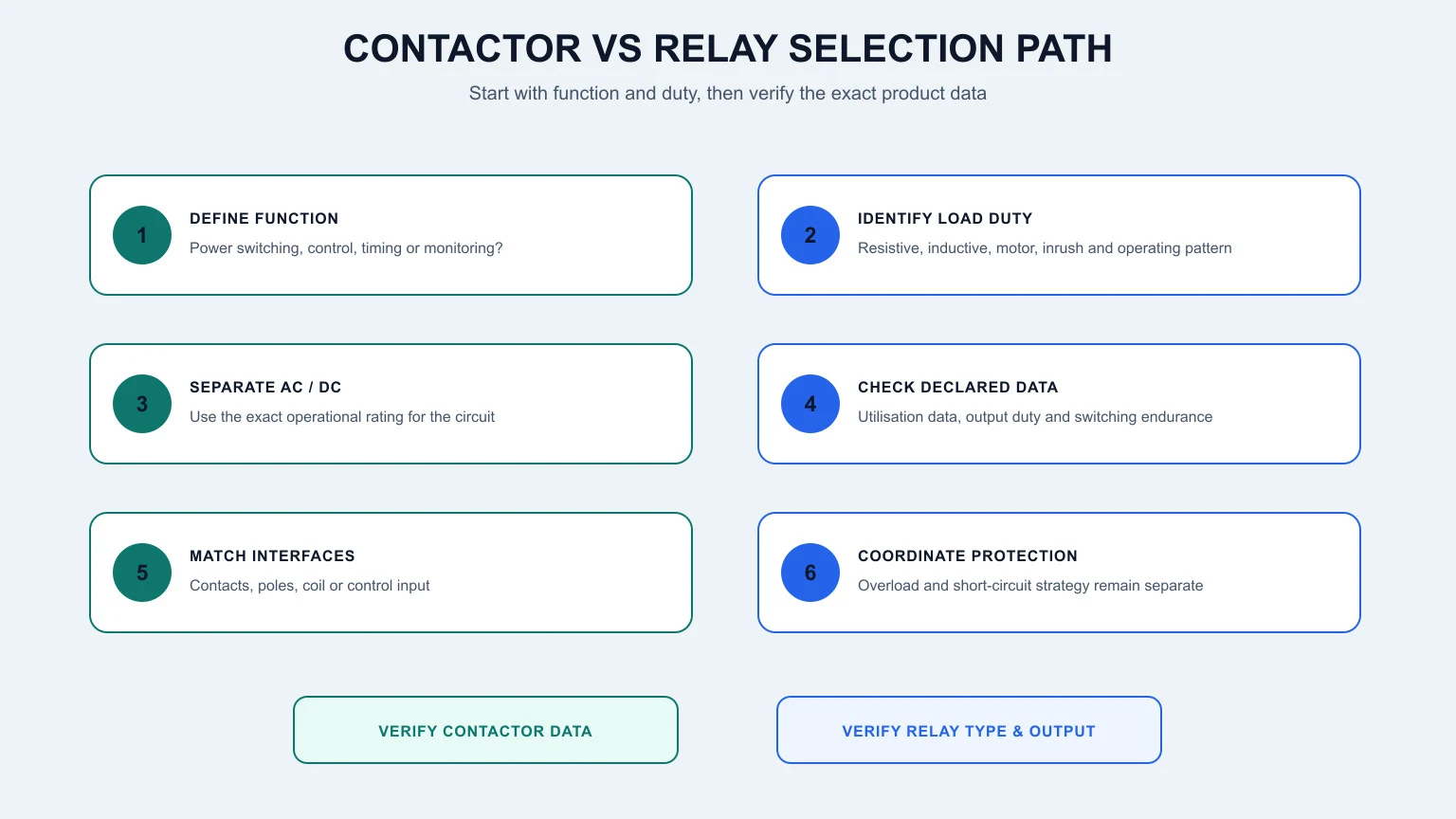
- Define the function. Decide whether the device must switch a power load, reproduce a control signal, introduce timing, monitor a condition or provide another defined function.
- Identify the load. Record load type, nominal current or power, starting or inrush behaviour and whether the duty is AC or DC.
- Check operational ratings. Use the manufacturer’s data for the exact load duty or utilisation category. Do not compare products only by the largest current printed on the front.
- Confirm contacts and poles. Match main contacts, auxiliary contacts, NO/NC arrangement and pole count to the circuit design.
- Verify the control supply. Check coil or input voltage, frequency where applicable, control-device output capability and suppression requirements.
- Assess operation and environment. Consider switching frequency, expected endurance, ambient temperature, enclosure conditions and required approvals.
- Coordinate protection. Confirm the short-circuit and overload protection strategy separately and follow the applicable product documentation and local rules.
Can a Relay and Contactor Be Used Together?
Yes. A relay and contactor often perform complementary roles. A timer, controller or interposing relay can issue the command, while the contactor performs the rated power switching. A separate protective device can address fault protection, and a correctly selected overload relay may form part of a motor-control arrangement.
For example, a timer relay may determine when a ventilation load should run. Its output controls the contactor coil, and the contactor switches the load circuit. This functional relationship does not define conductor sizes, terminal numbers, protective settings or an installation method.
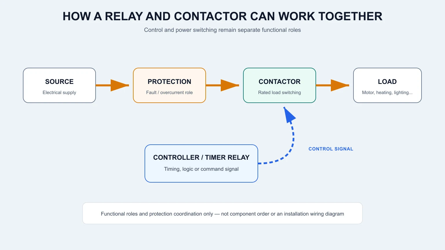
Simplified functional relationship only; not an installation wiring diagram. Final circuit design and verification must be completed by a competent person using the exact product documentation and applicable requirements.
Contactor vs Control Relay vs Overload Relay vs Circuit Breaker
| Device | Primary function | What it does not automatically replace |
|---|---|---|
| Contactor | Repeated switching of a rated load from a control signal | Short-circuit or overload protection |
| Control or timer relay | Control logic, signal switching, timing or sequencing | A contactor for an unverified power-load duty |
| Thermal overload relay | Detection of sustained motor overload when correctly applied | Short-circuit protection or general control logic |
| Circuit breaker | Interruption of specified fault or overcurrent conditions according to its design | A high-frequency routine switching device unless expressly rated for the duty |
This role separation is useful because product names can be misleading. A device called a “smart relay switch,” for example, may combine control, metering and protection-related functions that are not present in a conventional control relay. Always read the functional and rating data for the exact product.
ETEK Contactor and Timer Relay Examples
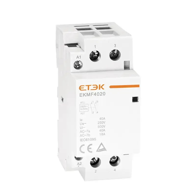
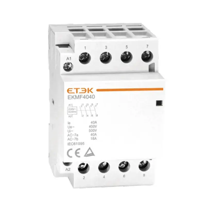
ETEK’s modular contactor selection guide explains the DIN-rail format, load-duty questions and 2P/4P selection in more detail. The EKMF 2P and EKMF 4P modular contactors are examples of devices intended for load switching in a modular format, subject to their exact ratings and documentation.
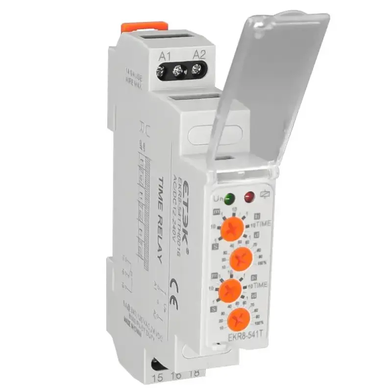
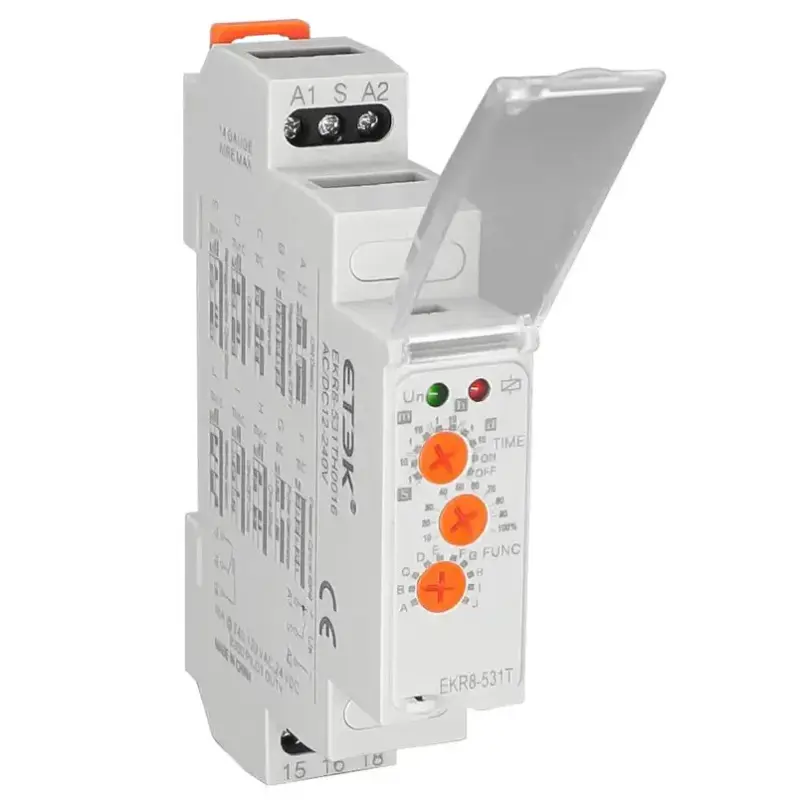
The EKR8-5 time relay is an example of a relay used to add a time-based control function. It should not be treated as representing every relay family, nor should its output be assumed suitable for a load without checking the contact rating and application.
Frequently Asked Questions
Can a relay replace a contactor?
Only when the exact relay is rated and approved for the complete switching duty. A similar nominal current is not enough. Check load type, AC or DC rating, inrush, switching frequency, contact endurance and manufacturer application data.
Is a contactor a type of relay?
A contactor and an electromechanical relay share a related electromagnetic switching principle. In practical product classification, a contactor is treated as a device designed for repeated switching of specified power loads, while relay is a broader family covering many control and monitoring functions.
Why are contactors commonly used for motors?
Contactors are available with ratings and utilisation data intended for motor-switching duties, including the effects of starting and repeated operation. The correct contactor still depends on motor characteristics, operating mode and coordination with protection.
Can a contactor switch a DC load?
Some contactors are rated for specific DC duties, but AC suitability does not establish DC suitability. Confirm the DC voltage, current, pole arrangement, load type and manufacturer documentation for the exact model.
What coil voltage should I choose?
The coil or control input must match the available control supply and the device driving it. Verify voltage range, AC or DC type, frequency where relevant, power consumption and any suppression or interface requirements.
Does a contactor or relay provide overload protection?
A standard contactor or control relay does not automatically provide overload or short-circuit protection. A thermal overload relay is a different device with a defined protective function, and short-circuit protection must be addressed separately.
What is the difference between a control relay and an overload relay?
A control relay changes contacts to perform logic, isolation or signal switching. An overload relay detects a sustained overload condition according to its design and contributes to motor protection. They solve different problems and are not substitutes.
Conclusion
The practical contactor vs relay decision starts with function and duty, not a fixed current number. Use a contactor when the exact product is rated for the required repeated power-load switching. Use the appropriate relay type for control, timing, monitoring or another defined relay function. Then verify contacts, AC/DC duty, inrush, switching frequency, control supply, environment and protection coordination before specification.