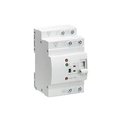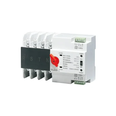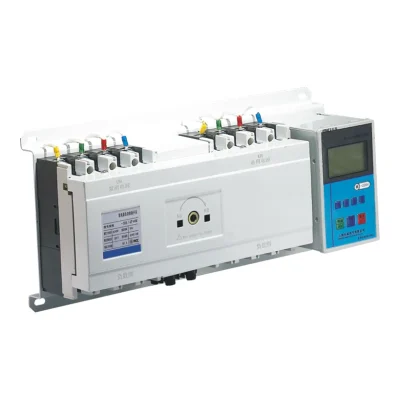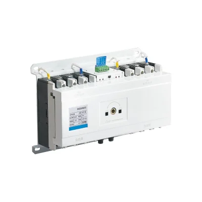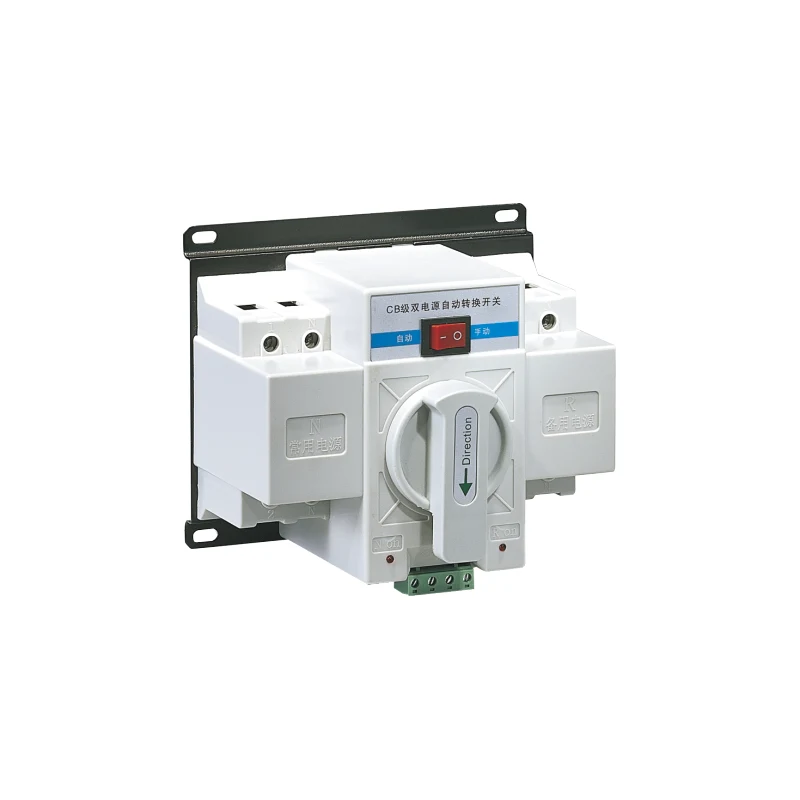
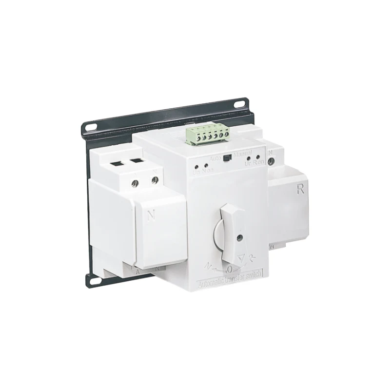
EKATS4 Dual Power Automatic Transfer Switch
● Control device: built in controller
● Product structure: small volume, high current, simple structure, ATS integration
● Features: fast switching speed, low failure rate, convenient maintenance and reliable performance
● Wiring mode: front plate wiring
● Conversion mode: power grid to power grid, power grid to generator, automatic switching and self recovery
● Product frame: 63
● Product current: 10,16,20,25,32,40,50,63A
● Product classification: circuit breaker
● Pole No.: 2, 3, 4
● Standard: GB/T14048.11-2008
● ATSE: CB class, with overload and short-circuit protection

Product Profile
Product Profile
EKATS4 series automatic power transfer switch (hereinafter referred to as transfer switch) is suitable for dual power supply system with AC 50Hz, rated working voltage 380V and rated working current up to 63A. it can complete the transfer between common power supply and standby power supply by automatic or manual operation. The switch is mainly used in hospitals, shops, banks, chemical industry, metallurgy, high-rise buildings, military facilities and other important occasions.
Working conditions
* The altitude of installation shall not exceed 2000m;
* The upper limit of ambient temperature is not higher than +40°C, the lower limit is not lower than -5°C, and the 24-hour average value is not higher than +35°C;
* The relative humidity of the atmosphere should not exceed 50% when the ambient air temperature is +40°C. At a lower temperature, there can be a higher humidity, and the condensation on the product surface should be considered when the temperature changes;
* There is no medium with explosion risk, and there is no gas and dust enough to corrode and destroy the insulation;
* No significant shake and shock vibration.
Basic structure
This series of automatic transfer switch is mainly composed of power transfer executive circuit breaker and controller. The switch has three working states for users to choose: common power (N) closing, double opening (manual) and standby power (R) closing. The switch has the advantages of small volume, light weight, stable operation and convenient use.
Product structure and characteristics
EKATS4 type intelligent dual power automatic transfer switch is made up of two units miniature circuit breaker and accessories (auxiliary contact, alarm contact), the mechanical interlocking transmission, controller and other components. 63A specification is composed of miniature circuit breaker, especially suitable for lighting and small motor control equipment. Its features is:
* The switch has the advantages of small volume, simple structure, convenient operation and long service life, which can be provided by 2P, 3P and 4P;
* Transfer switch driving by single motor, a smooth, no noise, the impact is small;
* With mechanical interlocking and electrical interlock, change over credibility, could be supply by manual or automatic operation;
* Common, standby circuit breaker rated current can be different;
* A.T.S is equipped with terminal for user wiring, which can reflect the status of circuit breaker (open or closed); there are various indications on A.T.S panel.
Working principle
This series of dual power supply controllers and driving mechanisms all use AC220V power supply, and their power supply signals depend on Phase A and Line N of the incoming ports of common switches or standby switches. When the dual power supply is in an automatic state, when the voltages of the incoming Phase A and Line N of the common switches are normal (AC190-240V), the common switches would be closed preferentially regardless of whether the voltages of the common power supply B, C and the standby switches A, B, C and N are normal. In the meantime, the power indicator and the common closing indicator are on. When there is no voltage on the incoming Phase A and Line N of the common switch and the voltage on the incoming Phase A and Line N of the standby switch is normal, the dual power supply will be turned to the standby closing regardless of whether the voltage on the normal and standby switches B and C is normal. The power indicator and the standby closing indicator are on. Manual function, no matter whether the common power supply and standby power supply have voltage or not, manual operation mode can be adopted. During manual operation, the manual-automatic button shall be placed in the manual operation position. When the push handle rotates clockwise to the terminal, the standby power circuit breaker R opens and the common power circuit breaker N closes. When the push handle rotates counterclockwise to the terminal, the standby power circuit breaker R closes and the common power circuit breaker N opens.
Installation and use
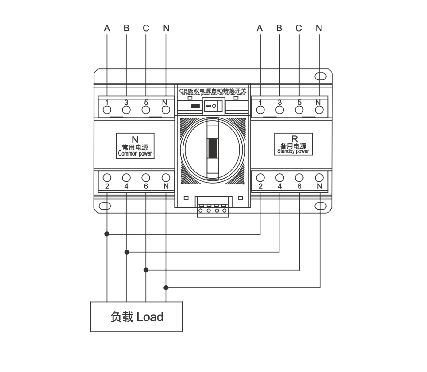
Before installation and use, check the appearance of dual power supply products and whether there is any damage during transportation. If there is any damage, contact the dealer in time. When wiring, please connect the three-phase and four-wire of the common and standby power supplies to the incoming terminals of the common and standby circuit breakers. Then the two circuit breakers are connected in parallel for load. If the selected dual power supply is three poles, the common zero line and the standby zero line must be connected to the dedicated terminal (not connected in reverse), otherwise the dual power supply will not work.
Note: During the installation and wiring process, do not forget the signal line originally connected to the incoming end of the circuit breaker, short circuit or open circuit.
Operation and maintenance
* Whether common power or standby power with voltage or not, all can be by manual mode operated. Under manual, put the auto-manual button to manual position, pull the handle by clockwise to end, standby power implementation circuit breaker Qr is OFF, implementation of common power supply circuit breaker Qn ON; When pull handle counterclockwise to the end, the implementation of standby power source Qr is ON, implementation of common power supply circuit breaker Qn is OFF;
* Set the auto position, if the common power is normally, ATS will transfer to common power working. The common power indication will bright on panel; If the common power is unusually, ATS will transfer to standby power working. The standby indication will be bright on the panel.
* ATS has 1A of two units fuses and a electric connector, fuse as short-circuit protection in automatic controller. The terminal provides active power for the indicator light to be connected to the control box panel, and its voltage is AC220V, current is 150mA, the specific operation can refer to the attached manual circuit diagram for connection.
Fault analysis and elimination
When the power supply changes in the automatic control state, the electric operating mechanism does not act, that is, the miniature circuit breaker cannot be closed or opened. At this time, check:
* Whether all power grids are cut off;
* Whether the wiring has fallen off;
* Whether the fuse of the product is blown. If there is power at the front end of any circuit breaker, and the wiring is correct and the fuse is in good condition, but it still can not be switched on or off, please ask professional personnel for maintenance or contact the manufacturer for solution.
Technical Data
Technical Data
A dedicated “Main technical parameters” table is not provided in the EKATS4 Series section of the PDF. Technical points available in this series section are listed below (from General / Product Overview only).
| Product frame | 63 |
|---|---|
| Product current | 10,16,20,25,32,40,50,63A |
| Rated working voltage | 380V |
| Rated frequency | AC 50Hz |
| Pole No. | 2, 3, 4 |
| Standard | GB/T14048.11-2008 |
| ATSE | CB class, with overload and short-circuit protection |
| Controller / drive power | AC220V |
| Common power preferential voltage range (Phase A and Line N) | AC190-240V |
| Indicator terminal output | AC220V, 150mA |
| Fuse in automatic controller | 1A of two units fuses |
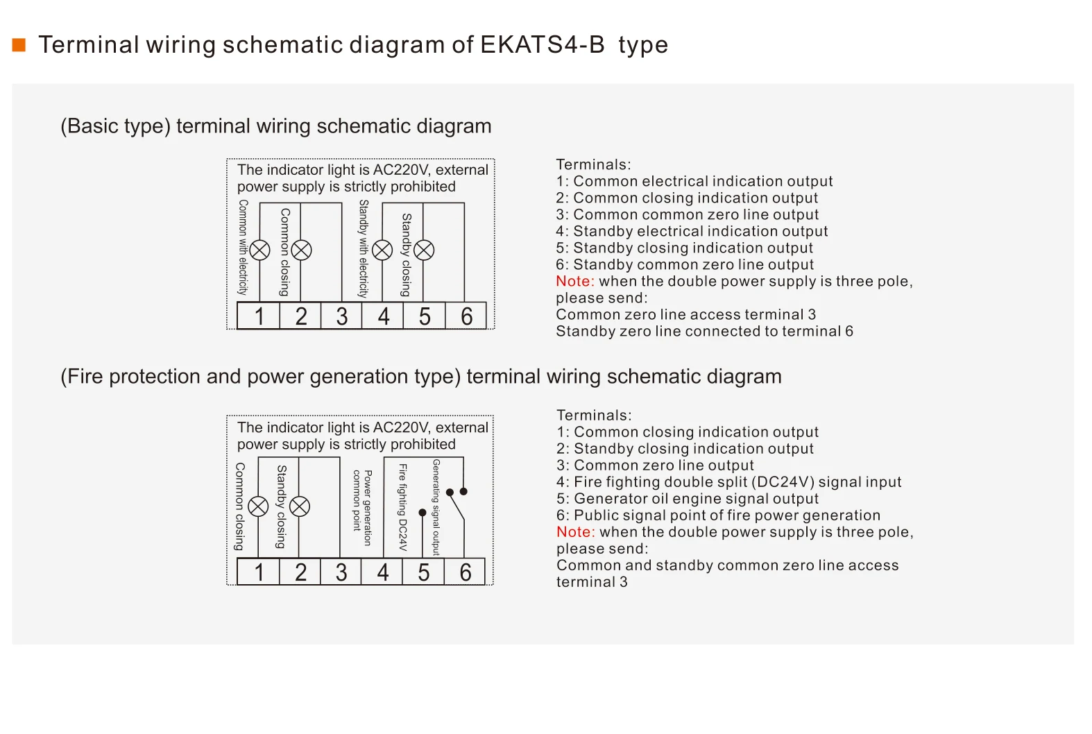
Operation and wiring diagram
Terminal wiring schematic diagram of EKATS4-A type
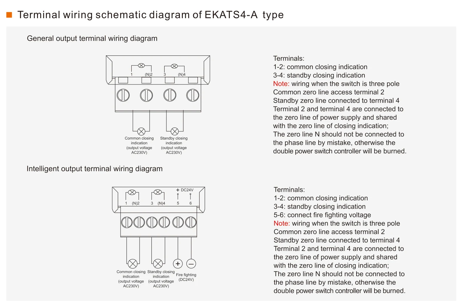
Terminal wiring schematic diagram of EKATS4-B type
Dimensions
Dimensions
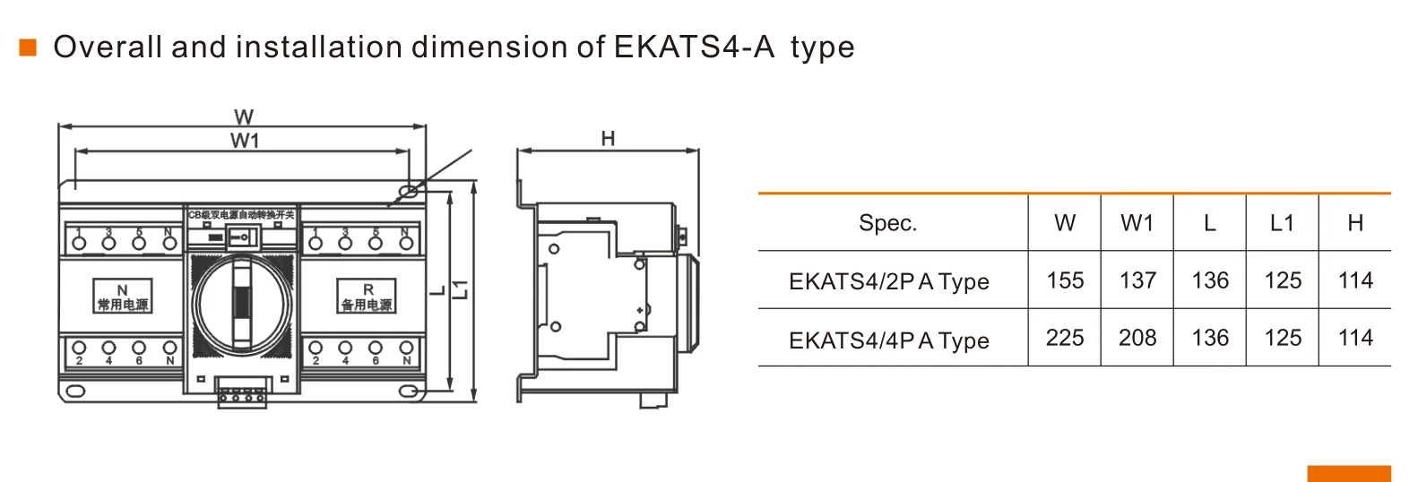
| Spec. | W | W1 | L | L1 | H |
|---|---|---|---|---|---|
| EKATS4/2P A Type | 155 | 137 | 136 | 125 | 114 |
| EKATS4/4P A Type | 225 | 208 | 136 | 125 | 114 |
Overall and installation dimension of EKATS4-B type
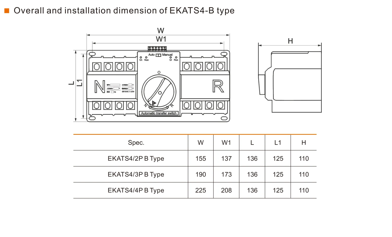
| Spec. | W | W1 | L | L1 | H |
|---|---|---|---|---|---|
| EKATS4/2P B Type | 155 | 137 | 136 | 125 | 110 |
| EKATS4/3P B Type | 190 | 173 | 136 | 125 | 110 |
| EKATS4/4P B Type | 225 | 208 | 136 | 125 | 110 |