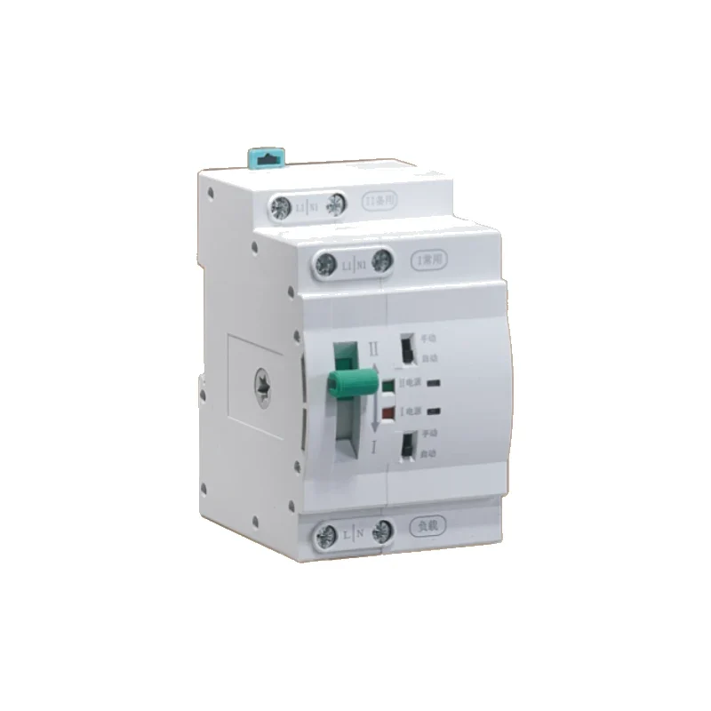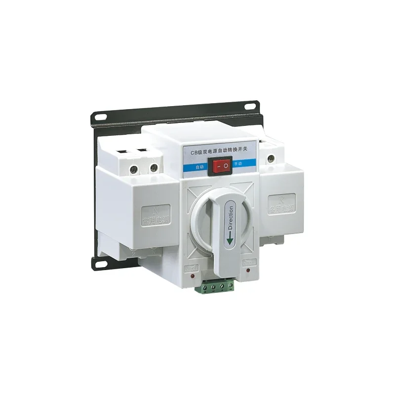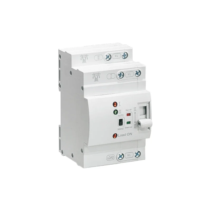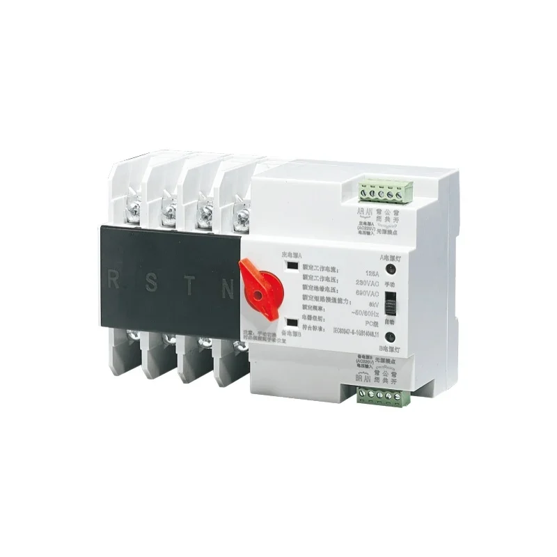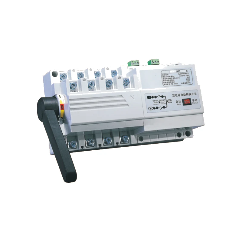
EKATS6 Dual Power Automatic Transfer Switch
● Control device: built in controller
● Product structure: small volume, high current, simple structure, ATS integration
● Features: fast switching speed, low failure rate, convenient maintenance and reliable performance
● Wiring mode: front plate wiring
● Conversion mode: power grid to power grid, power grid to generator, automatic switching and self recovery
● Product frame: 125,250,630
● Product current: 16,20,32,40,63,80,100,125,160,180,200,225,250,315,400,500,630A
● Product classification: load switch type
● Pole No.: 4
● Standard: GB/T14048.11-2016
● ATSE: PC class

Product Profile
Product Profile
* EKATS6 Automatic transfer switch (ATSE) is set the switches and control logic integrated without additional controller, achieve integration of automatic electromechanical switch. It has functions such as voltage detection, electrical and mechanical interlocking, and can achieve automatic and emergency manual control.
* This is the logical control panel from various logical order to manage the machines, operate with the gearbox to achieve, switching spring motor storage, instantaneous release of the acceleration, rapid access to sub-circuit or circuits conversion, it is obvious by the state security confinement, greatly improved the performance of various electrical and mechanical properties.
* The switches overall design with compact solid. The switching components used fiberglass unsaturated polyester resin manufacturing, with a strong dielectric properties, protection and reliability of the operational safety.
* Switch power supply system applicable to changeover the main power supply and backup power supply automatically or two sets load equipment and safety isolation automatically.
* Switch appearance is beautiful, creative, simple, small size, the entire function is an ideal choice in different occasions.
Meeting the standards
* IEC60947-1(1998)/GB/T14048.1-2002 "Low voltage switchgear and control equipment General rules"
* IEC60947-3(1999)/GB14048.3-2002 "Low voltage switchgear and control equipment, low voltage switch, isolator, disconnector and fuse combination apparatus"
* IEC60947-6(1999)/GB14048.11-2016 "Low voltage switchgear and controlgear multifunction electrical apparatus part 1: automatic transfer switchgear"
Scope of application
* EKATS6 series dual power automatic transfer switch is mainly applicable to the AC 50Hz, rated voltage AC400V, working voltage 220V, rated current 16A to 630A distribution or generator network. There is a primary and standby power, or as the utility to generator in loading changeover. At the meanwhile, it can be used for isolation of infrequently connecting and breaking circuits and lines.
* This products are widely used in hospitals, banks, high-rise architecture and so on, which are very important place disallow the failure to supply, distribution and automation system.
Performance and characteristics
* Adopt the double row type composite contact, side pull institutions, micro motor prestore and microelectronics control technology, come true zero flashover (no arcing chamber).
* Reliable electrical and mechanical interlocking chain, the implement of the components independently with isolation switch, the use of safe and reliable.
* Using over zero technology, the state of emergency can be enforced under the zero (cut down the 2 ways in the meanwhile) to meet the needs of fire fighting.
* Executive load isolation switch using a single motor-driven, transfer reliable smooth, no noise, little impact.
* Operators drive only in the implementation of the electrical load isolation by switching transient current, steady work without providing current, energy-saving significantly.
* Executive load isolation switch with a mechanical device used to ensure that reliable standby power of non-interference in each other.
* With function of obvious on-off position indication, high reliability and service life of more than 8000 times.
* Mechatronics design, switching conversion accurate, flexible, smooth and adopt international advanced logic control technology, anti-interference capability, without external interference.
* Cooperation with the main power on and standby power off, or the main power off and standby on, the main power and standby power are both off, three kinds stability working (I-O-II).
* Easy installation, the control circuit return way adopt the connect and insert terminal connector.
* Four operator models: emergency manual operation, emergency disconnected operation under the automatic stating, automatic control operations.
Switch structure description
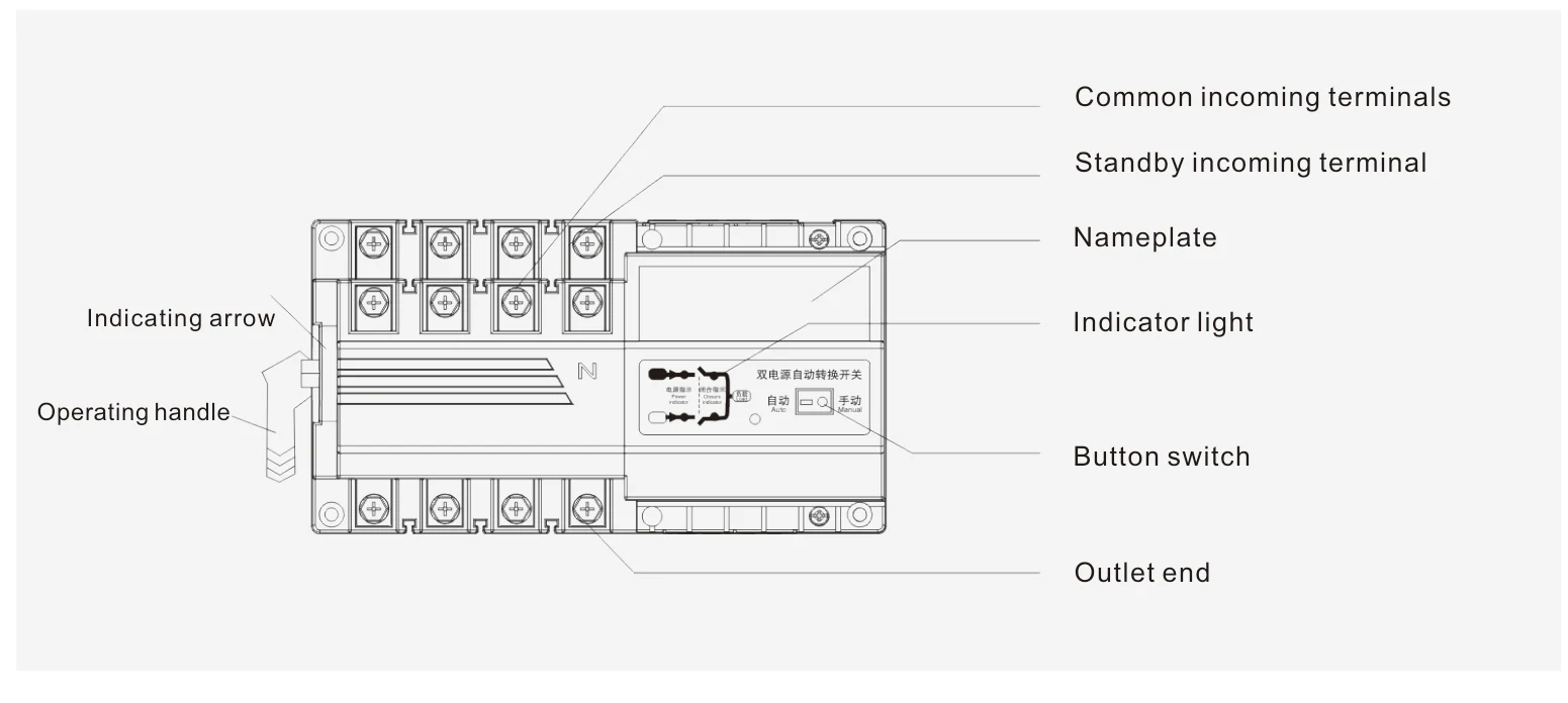
1. Electrical button switch: control switch internal control line power supply. When the button switch is on, the switch can be fully automatic. When the button switch is off, the switch can only be operated manually.
2. Operating handle: when using the operating handle for manual operation, the button switch must be turned off first.
3. Indicator: indicates the three states (I, 0, II) of the switch, "I" indicates that switch I is on, "II" means switch II is on, "0" indicates that switch I and switch II are all disconnected.
Technical Data
Technical Data
* Rated working voltage (Ue): AC400V;
* Rated making capacity (ARms): 10Ie.
Additional technical points from General / Scope of application (same series only):
| Product frame | 125,250,630 |
|---|---|
| Product current | 16,20,32,40,63,80,100,125,160,180,200,225,250,315,400,500,630A |
| Rated frequency | AC 50Hz |
| Working voltage | 220V |
| Pole No. | 4 |
| Standard | GB/T14048.11-2016 |
| ATSE | PC class |
| Product classification | load switch type |
| Service life | more than 8000 times |
Switch control type and corresponding function
1) Type I: fully automatic, optional with generator function.
2) Type II: fully automatic, fire control double split, fire feedback signal, generator function signal.
3) Type III: Phase loss detection and protection, full-automatic, fire-fighting double split, fire-fighting feedback signal, generator function signal.
4) Full automatic: automatic switch and automatic recovery. When the common power supply is cut off (or the phase is broken), the switch will automatically switch to the standby power supply; when the common power supply returns to normal, the switch will automatically return to switch to the common power supply.
5) Fire control double points: in case of emergency or equipment maintenance, start the fire power supply (constant voltage), switch to "0" position automatically and cut off the dual power supply.
6) When the switch is switched to "0" position, the passive feedback signal is output.
7) With generator (oil engine): when the mains power is cut off (or the phase is broken), it will send the oil engine start signal to make the oil engine start automatically. After the power generation is normal, the switch will automatically switch to the power generation power supply. When the mains power supply returns to normal, the switch will automatically return to the mains power supply and send the oil engine shutdown signal to automatically shut down the oil engine.
8) Phase loss detection and protection: detect and protect the outage of any phase of the common (standby) power supply.
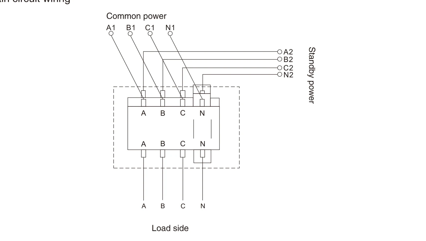
Switch wiring method
Main circuit wiring
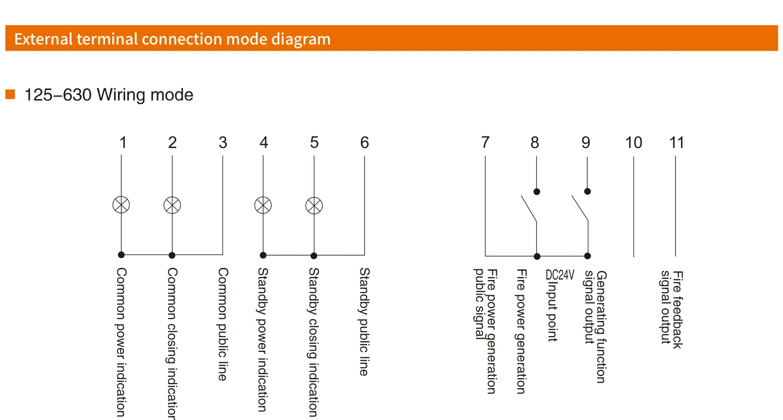
External terminal connection mode diagram
125–630 Wiring mode
Switch Debugging Instructions
1. Use the operating handle and operate the switch three times repeatedly. The switch should be operated flexibly.
2. Fully automatic debugging: connect the corresponding line according to the wiring diagram, turn on the button switch after confirming that there is no error, and then turn on the double power supply, and the switch should be turned to "I"; then disconnect the common power supply, the switch should be turned to the "II" position; and then turn on the common power supply, the switch should return to the "I" position.
3. Fire debugging: under normal power on, start the fire power button, the switch should be turned to the "0" position.
4. Detection signal indicator: when the common/standby power supply is on/off, when the switch "I/II" is on or off, each signal indicator shall give corresponding indication.
5. After debugging, please turn off the power supply first, and then turn the switch to "0" position with the handle.
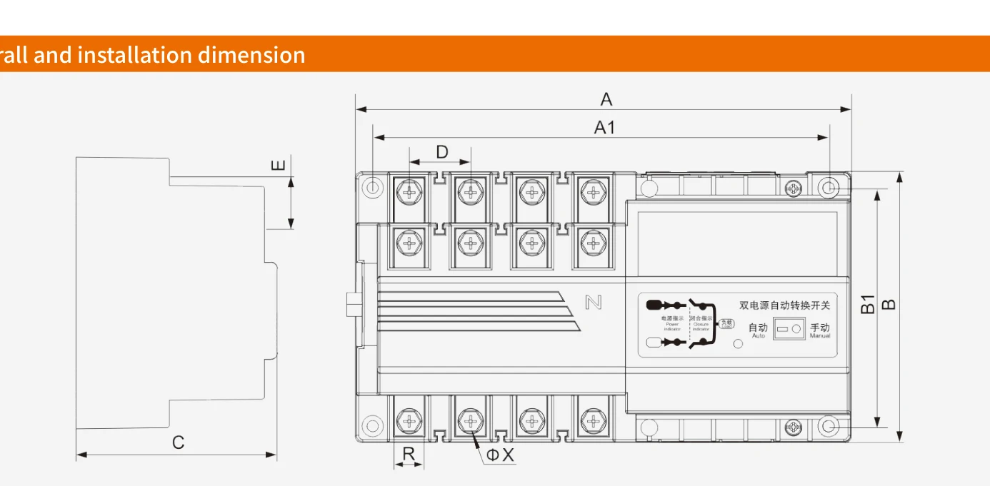
Dimensions
Dimensions