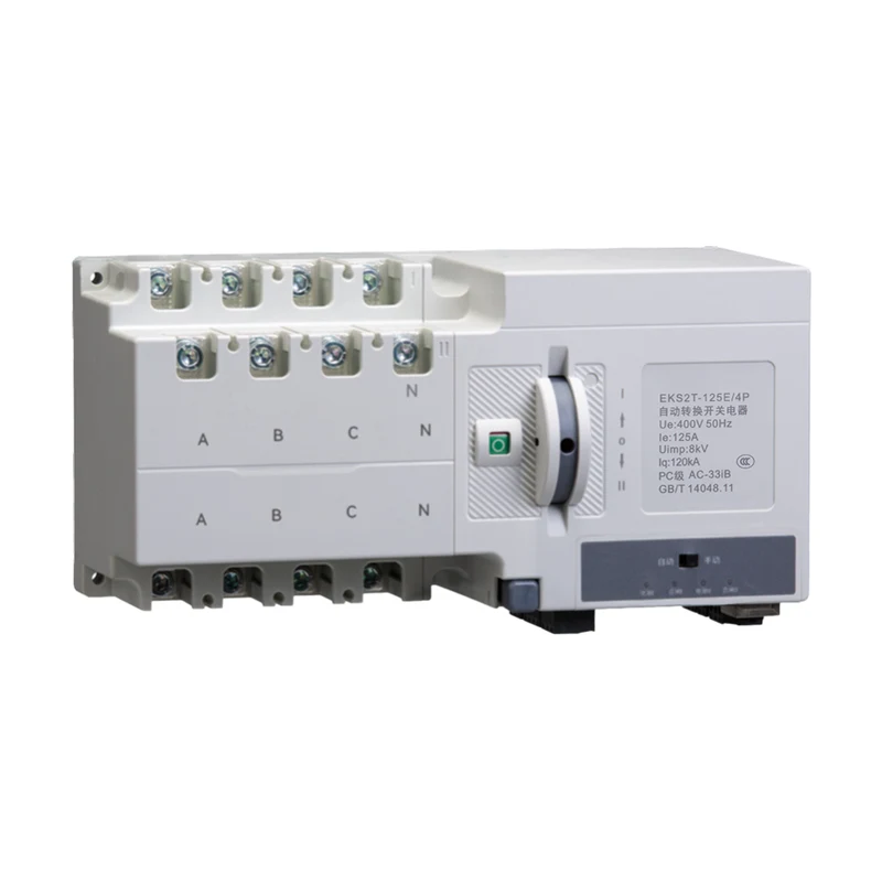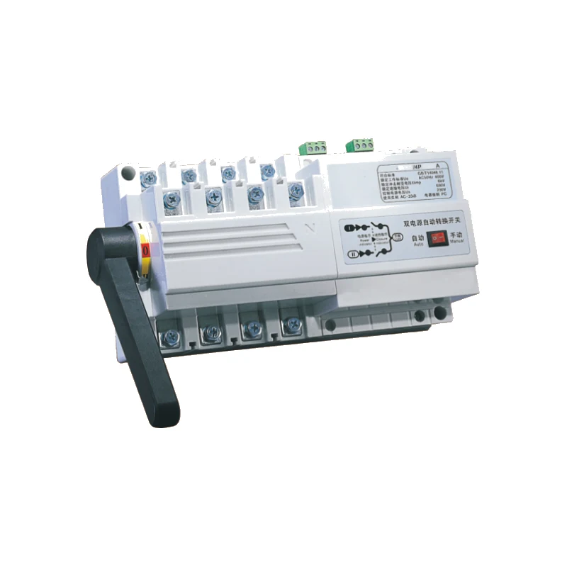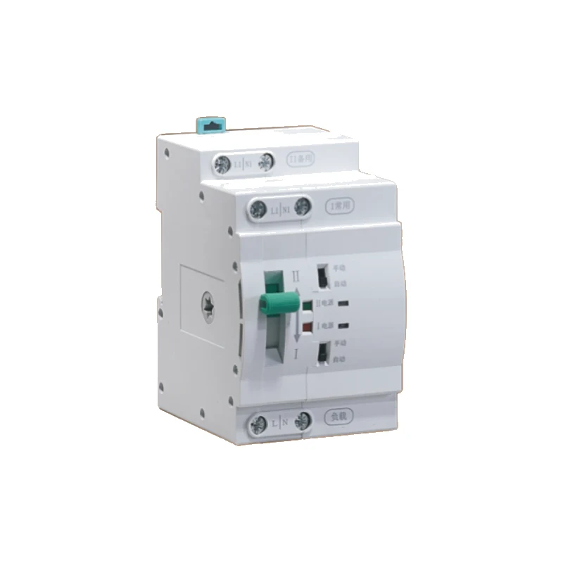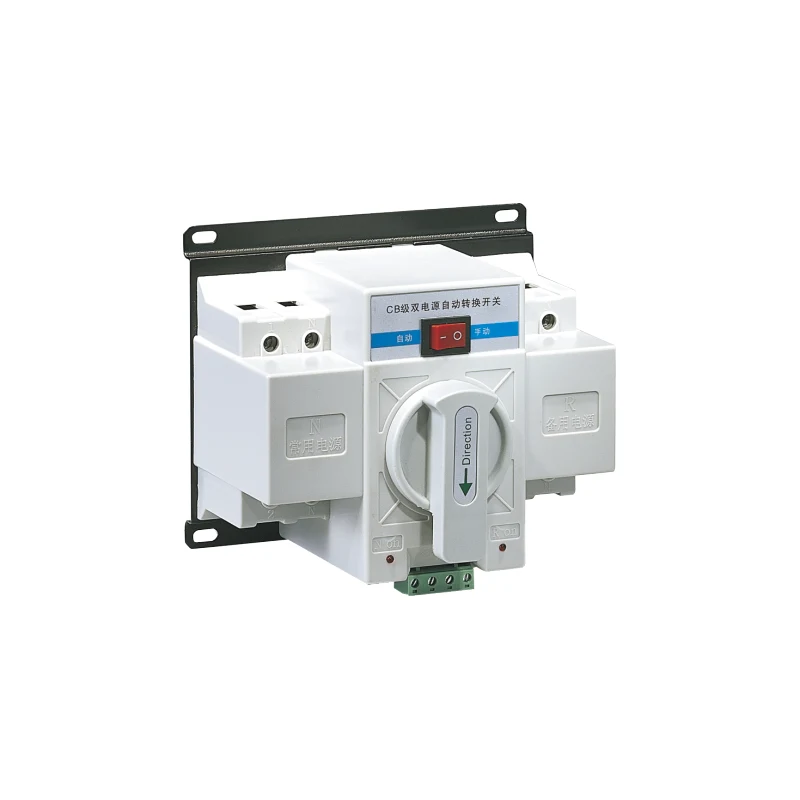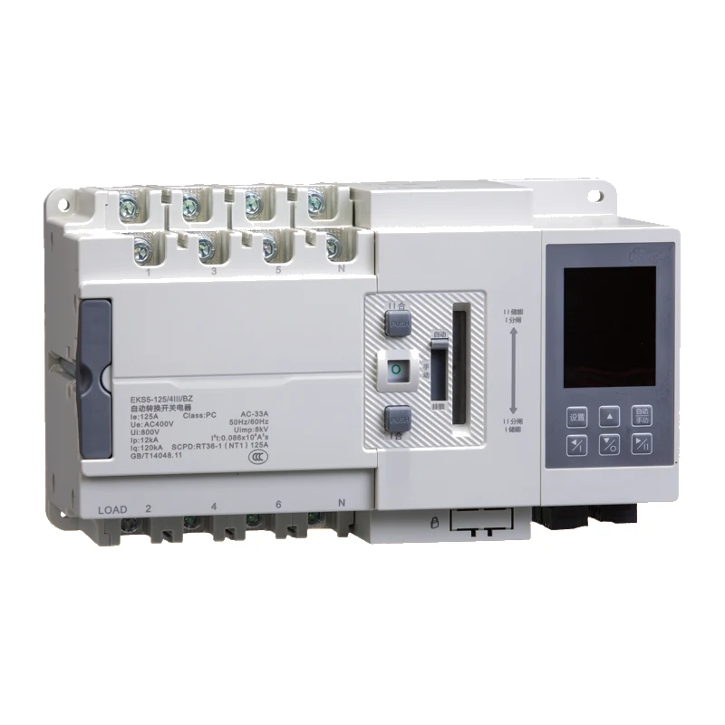
EKS5 Dual Power Automatic Transfer Switch
● Product type: PC grade specialized automatic transfer switching electric device
● Product structure: integrated type / split type; two-sectional type / three-sectional type contact positions
● Features: fast transfer speed; applicable category up to AC-33A; high rated limited short-circuit current with circuit breakers and fuses used as SCPD; complete functions and high intelligence
● Conversion mode: switchover between power supplies when one becomes abnormal; self-throwing self-resetting / self-throwing non-self-resetting / mutually backup modes
● Product frame: 125, 250, 400, 630
● Product current: 16A to 630A
● Pole No.: 2P, 3P, 4P (by shell frame)
● Rated working voltage: AC220/230V (2P), AC400/415V (3P/4P)
● Rated working frequency: 50/60Hz
● Standard: GB/T14048.11
● ATSE: PC class
● Minimum converting action time: 70ms (125A/250A), 100ms (400A/630A)
● Controller: Type A (standard type), Type B (high grade type)

Product Profile
Product Profile
EKS5 series high-performance automatic conversion switchgear (hereinafter referred to as device) is a PC grade specialized automatic transfer switching electric device, mainly used for the power supply system of AC 50/60Hz, rated working voltage AC220/230, AC400/415V and a rated working current of 16A to 630A to do switchover between the power supplies in case one of them becomes abnormal so as to ensure its continuity and reliability in power supply.
This device holds such features as a fast transfer speed, an applicable category up to AC-33A and, with circuit breakers and fuses used as SCPD, a high rated limited short-circuit current, two/three two positions with the contact, complete functions and high intelligence. Suitable for various important power supply places such as construction, industry finance, medical, communication, data centers, airports, rail transit, sports venues, etc.
This device complies with the standard GB/T14048.11.<>
Normal working conditions
* The ambient air temperature -5°C ~ +40°C, the average value over 24 hours not exceed by +35°C
* The altitude of the installation site not exceeded by 2000m;
* At a maximum temperature of +40°C, the relative air humidity not exceeded by 50%. At lower temperatures, allowed with a higher relative humidity, such as reaching 90% at 20°C. Special measures should be taken for occasional condensation caused by temperature changes;
* The pollution level comes as 3;
* Transportation, storage, and installation conditions: the device must not be affected by rain or snow during transportation. The storage environment temperature shall be between -25°C and +80°C, when the relative humidity is not be exceeded by 95% (at 25°C), and can be reached to +85°C in case of a short period of time (not exceeding 24 hours).
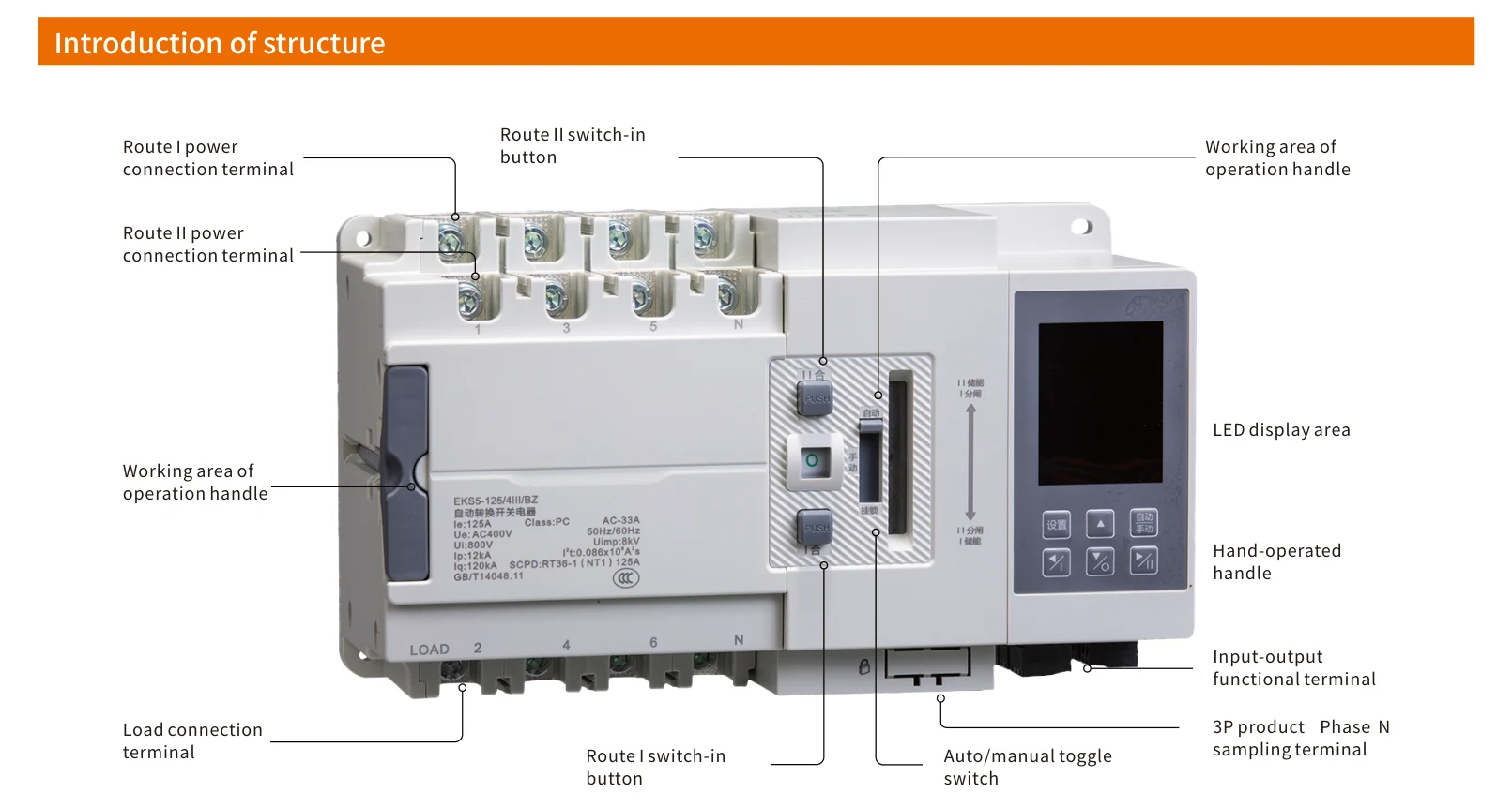
Introduction of structure
Introduction of display panel
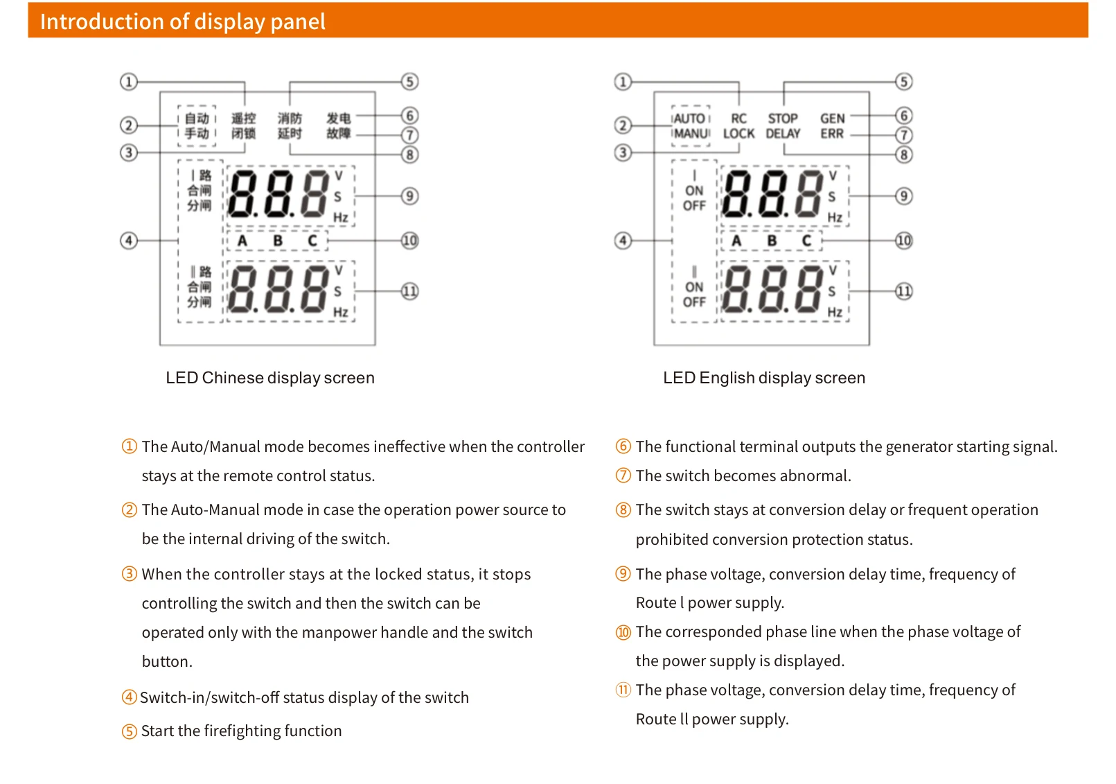
① The Auto/Manual mode becomes ineffective when the controller stays at the remote control status.
② The Auto-Manual mode in case the operation power source to be the internal driving of the switch.
③ When the controller stays at the locked status, it stops controlling the switch and then the switch can be operated only with the manpower handle and the switch button.
④ Switch-in/switch-off status display of the switch
⑤ Start the firefighting function
⑥ The functional terminal outputs the generator starting signal.
⑦ The switch becomes abnormal.
⑧ The switch stays at conversion delay or frequent operation prohibited conversion protection status.
⑨ The phase voltage, conversion delay time, frequency of Route I power supply.
⑩ The corresponded phase line when the phase voltage of the power supply is displayed.
⑪ The phase voltage, conversion delay time, frequency of Route II power supply.
Model Preparation Meaning
Model Preparation Meaning
Definition of model
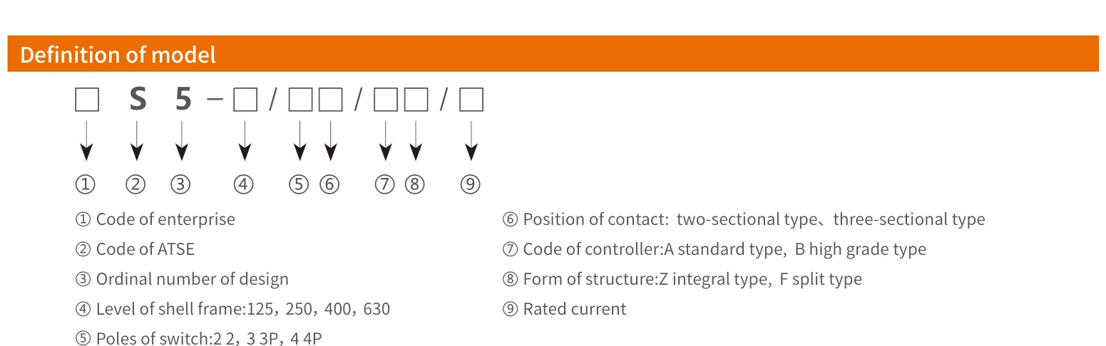
① Code of enterprise
② Code of ATSE
③ Ordinal number of design
④ Level of shell frame: 125, 250, 400, 630
⑤ Poles of switch: 2 2P, 3 3P, 4 4P
⑥ Position of contact: two-sectional type, three-sectional type
⑦ Code of controller: A standard type, B high grade type
⑧ Form of structure: Z integral type, F split type
⑨ Rated current
Technical Data
Technical Data
| Shell frame current | 125A | 250A | 400A | 630A |
|---|---|---|---|---|
| Poles of switch | 2P, 3P, 4P | 3P, 4P | 3P, 4P | 3P, 4P |
| Rated working current | 16A, 20A, 32A, 40A, 50A, 63A, 100A, 125A | 125A, 160A, 200A, 225A, 250A | 250A, 315A, 400A | 400A, 500A, 630A |
| Category at use | AC-33A | AC-33iA | ||
| Rated working frequency | 50/60Hz | |||
| Rated working voltage | AC220V/230V (2P), AC380V/400V (3P/4P) | |||
| Rated voltage of controlling power supply | AC230V | |||
| Rated insulation voltage | 800V | |||
| Rated impulse-resistant voltage | 8kV | |||
| Rated limited short-circuit current | 120kA | |||
| SPCD fuse parameters Ip | 12kA | 27kA | 42kA | 59kA |
| SPCD fuse parameters I²t | 0.068×10⁶A²s | 0.3×10⁶A²s | 2.0×10⁶A²s | 3.9×10⁶A²s |
| Minimum converting action time | 70ms | 100ms | ||
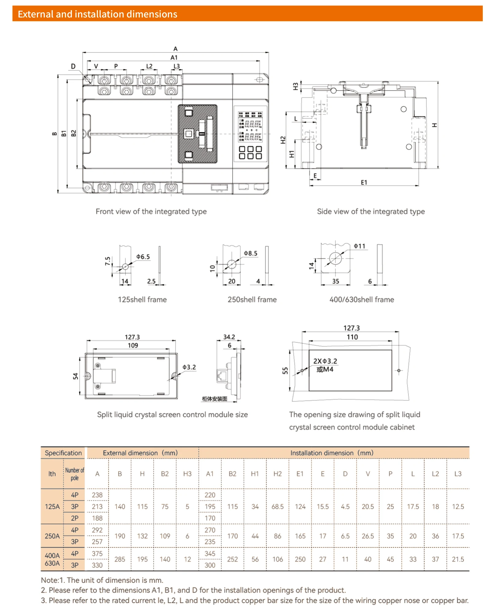
| External dimension (long × wide × deep) | 238mm×140mm×115mm | 292mm×190mm×132mm | 375mm×285mm×195mm | |
Functional parameters
| Functional items of controller type | Type A (standard type) | Type B (high grade type) |
|---|---|---|
| Rated control power supply | AC230V 50/60Hz | |
| Assistant working power supply voltage | DC24V | |
| Number of contact working positions | Two-sectional type / three-sectional type | |
| Operation mode | Auto-operation handle operation | Auto-operation handle operation, Split operation, Communication remote control |
| Way of conversion | Self throwing self resetting | Self throwing non-self resetting |
| Way of display | LED digital screen display (integrated type) / LCD screen display (split type) | |
| Common monitoring power supply | Monitoring of phase failure, under-voltage, overvoltage, and lost-voltage (A, B, C three-phase) | |
| Backup monitoring power supply | Monitoring of phase failure, under-voltage, overvoltage, and lost-voltage (A, B, C three-phase) | |
| Generator control | Available (with a set of relay dry contact) | |
| Fire fighting linkage control | Defaulted: unavailable, functional module can be added | Firefighting avoidance (one set of passive contact inputs, one set of normally open passive signal feedback) |
| Power supply over/under frequency detection | 40Hz~60Hz adjustable | |
| Timing start function | None | Timing conversion |
| Conversion delay | Standard allocation: 0.5s, 0~180s continually adjustable | |
| Return delay | Standard allocation: 0.5s, 0~180s continually adjustable | |
| Under-voltage setup range | 161V~196V adjustable (defaulted 187V, detection accuracy ±3V), with a hysteresis value of 10V | |
| Over-voltage setup range | 242V~301V adjustable (defaulted 263V, detection accuracy ±3V), with a hysteresis value of 10V | |
| Main-power selection | Route I priority: b-3 menu 0 means common priority, as the defaulted setting. Route II priority: b-3 menu 1 means standby priority. | |
| Communication function | None | 301-303 are communication ports, as A+, B- and GND RS485 interfaces, respectively, Modbus protocol |
| Way of installation | Integrated type | Split type |
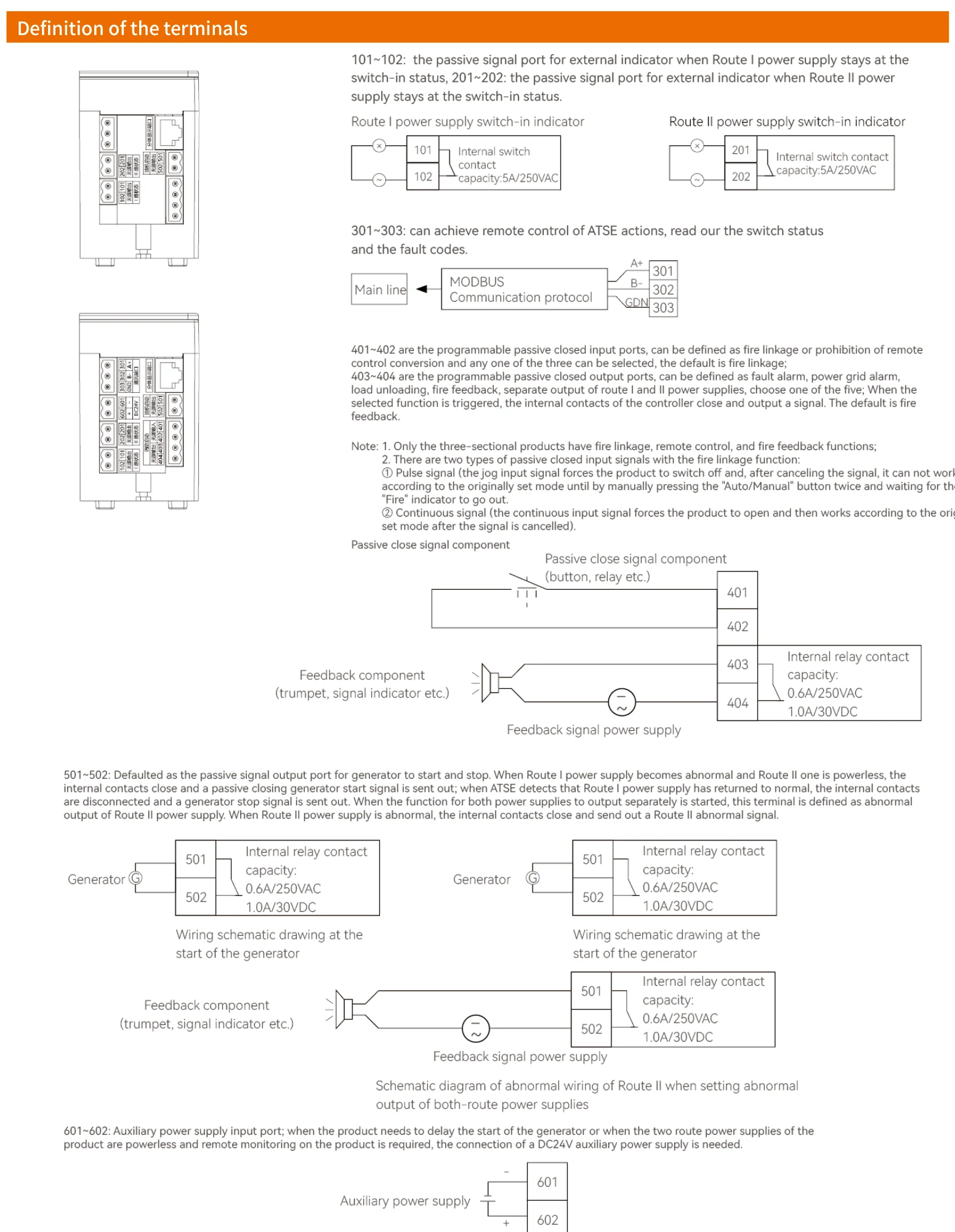
Type B controller fire linkage control port, as a programmable port, the defaulted function comes as fire linkage control; and, if so required, it can be changed into such functions as fault alarm, power grid alarm, load unloading, remote power-off, short circuit locking, etc.
Definition of the terminals
Twice terminal wiring diagram
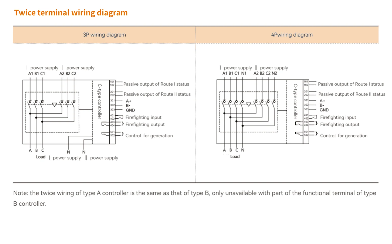
Note: the twice wiring of type A controller is the same as that of type B, only unavailable with part of the functional terminal of type B controller.
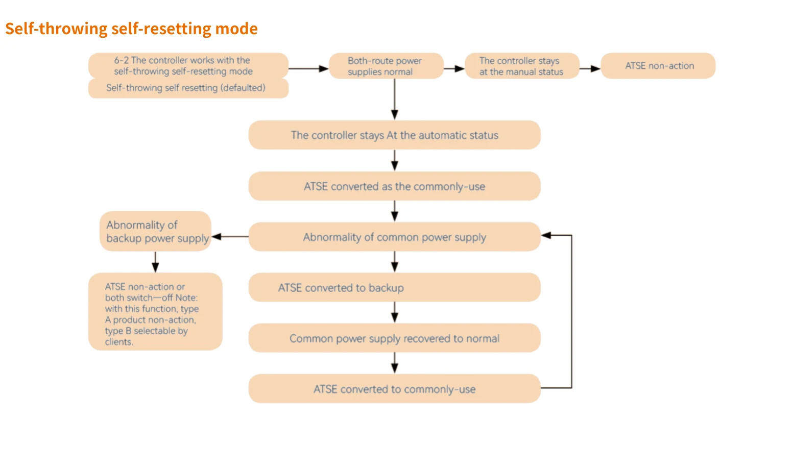
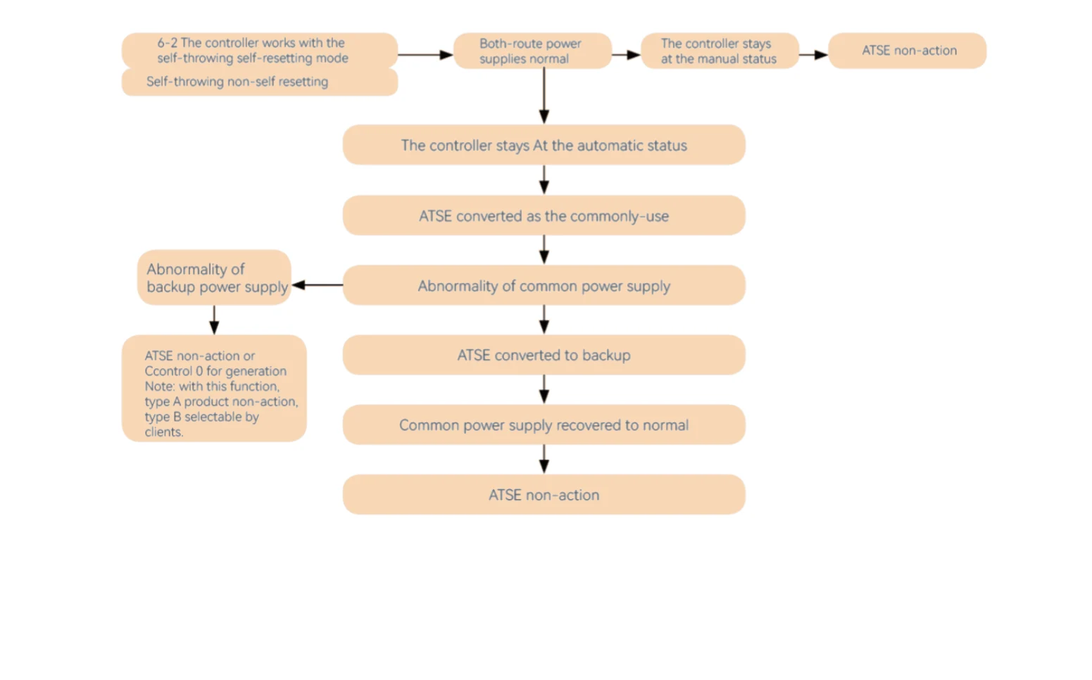
Self-throwing self-resetting mode
Self-throwing non-self-resetting mode
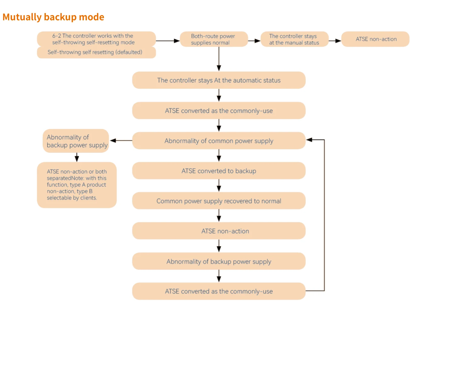
Mutually backup mode
Dimensions
Dimensions