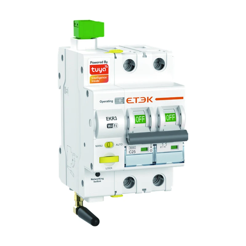
EKR3 WiFi Smart MCB | Tuya Remote Control
● Product type: Smart MCB (Miniature Circuit Breaker)
● Series / variant: EKR3 RS485
● Communication method code: 5 = RS485
● Functions: Overload protection, short-circuit protection, remote closing and timing control, real-time switch status monitoring
● Operation modes: Automatic mode (remote control via RS485); Manual mode (local operation only)
● No. of poles: 1P, 2P, 3P, 4P
● Rated currents (In): 10, 16, 25, 32, 40, 50, 63A
● Rated voltage (Ue): 240V (1P, 2P), 415V (3P, 4P)
● Rated short-circuit capacity (Icn): 6kA
● Trip curve: B, C
● RS485 baud rate: 2400 / 4800 / 9600 (default)
● Installation: Mounting on 35mm DIN rail; incoming method from top
● Protection degree: IP20

Product Profile
Product Profile
Overview
EKR3 smart MCB provides not only overload and short-circuit protection like traditional circuit breakers, but also the ability to remotely control the closing and timing of the MCB through the Tuya APP or RS485 platform, as well as obtain the switch status of the device.
EKR3 smart MCB is an ideal choice for smart home and industrial automation systems, offering circuit protection, remote control, and monitoring capabilities to improve energy management efficiency, enhance power safety, and provide users with more control options.
This product page is for the WiFi (Tuya) communication variant of EKR3 (type code communication method: 0).
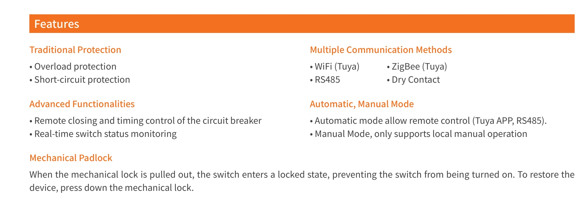
Features
Traditional Protection
- Overload protection
- Short-circuit protection
Advanced Functionalities
- Remote closing and timing control of the circuit breaker
- Real-time switch status monitoring
Multiple Communication Methods
- WiFi (Tuya)
- ZigBee (Tuya)
- RS485
- Dry Contact
Automatic, Manual Mode
- Automatic mode allows remote control (Tuya APP, RS485).
- Manual Mode, only supports local manual operation
Mechanical Padlock
When the mechanical lock is pulled out, the switch enters a locked state, preventing the switch from being turned on. To restore the device, press down the mechanical lock.
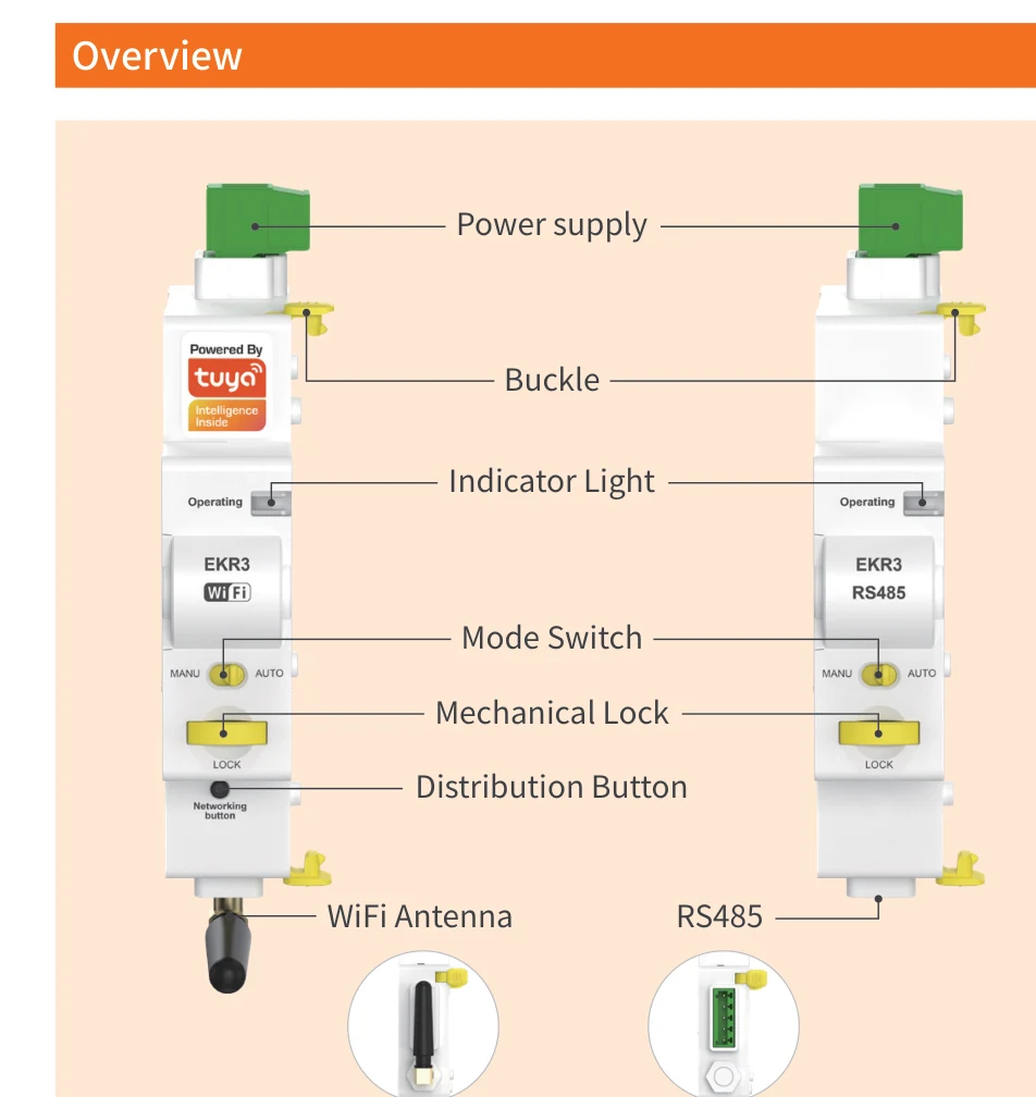
Introduction of structure

Structure labels from the catalog: Power supply, Buckle, Indicator Light, Mode Switch, Mechanical Lock, Distribution Button, WiFi Antenna, RS485.
485 Dry contact terminals: 485A, 485B, Dry contact G, IN1, IN2.
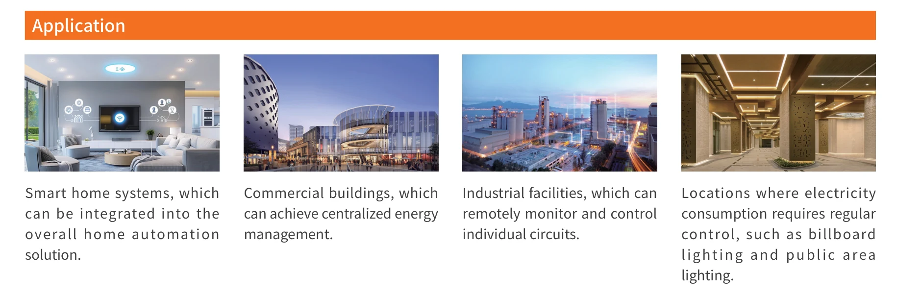
Application
- Smart home systems, which can be integrated into the overall home automation solution.
- Commercial buildings, which can achieve centralized energy management.
- Industrial facilities, which can remotely monitor and control individual circuits.
- Locations where electricity consumption requires regular control, such as billboard lighting and public area lighting.
Model Preparation Meaning
Model Preparation Meaning
Instruction of Type Code
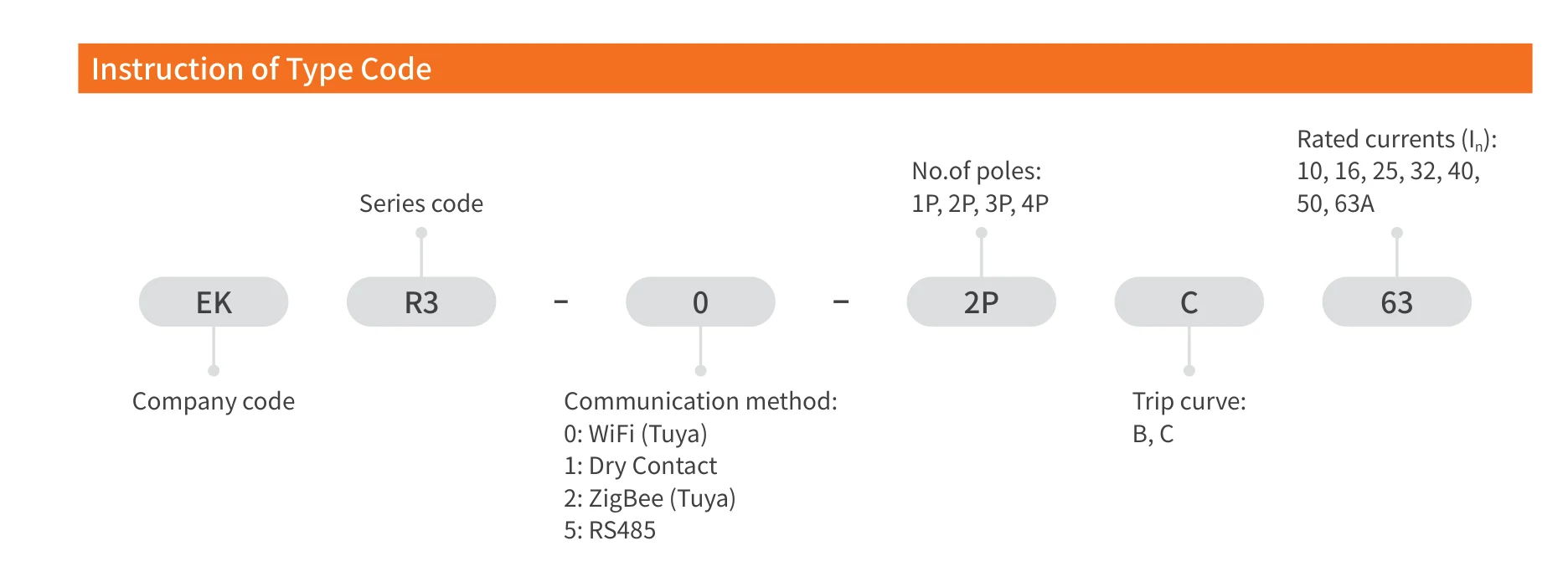
Example type code structure: EK R3 - 0 - 2P C 63
- EK — Company code
- R3 — Series code
- 0 — Communication method (this product: 0 = WiFi (Tuya))
- 0: WiFi (Tuya)
- 1: Dry Contact
- 2: ZigBee (Tuya)
- 5: RS485
- 2P — No. of poles: 1P, 2P, 3P, 4P
- C — Trip curve: B, C
- 63 — Rated currents (In): 10, 16, 25, 32, 40, 50, 63A
Technical Data
Technical Data
Technical Parameter
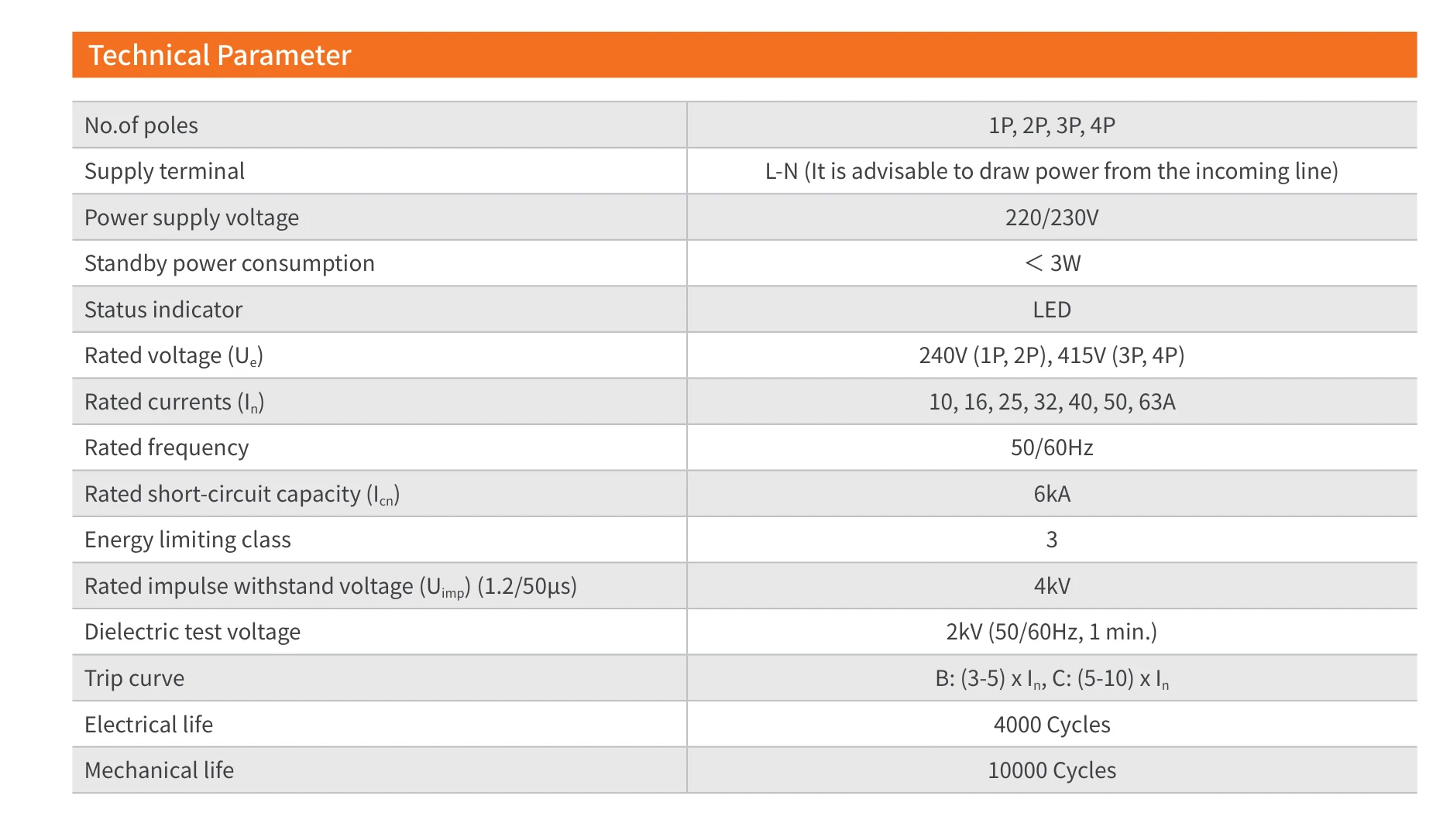
| No. of poles | 1P, 2P, 3P, 4P |
|---|---|
| Supply terminal | L-N (It is advisable to draw power from the incoming line) |
| Power supply voltage | 220/230V |
| Standby power consumption | < 3W |
| Status indicator | LED |
| Rated voltage (Ue) | 240V (1P, 2P), 415V (3P, 4P) |
| Rated currents (In) | 10, 16, 25, 32, 40, 50, 63A |
| Rated frequency | 50/60Hz |
| Rated short-circuit capacity (Icn) | 6kA |
| Energy limiting class | 3 |
| Rated impulse withstand voltage (Uimp) (1.2/50μs) | 4kV |
| Dielectric test voltage | 2kV (50/60Hz, 1 min.) |
| Trip curve | B: (3-5) x In, C: (5-10) x In |
| Electrical life | 4000 Cycles |
| Mechanical life | 10000 Cycles |
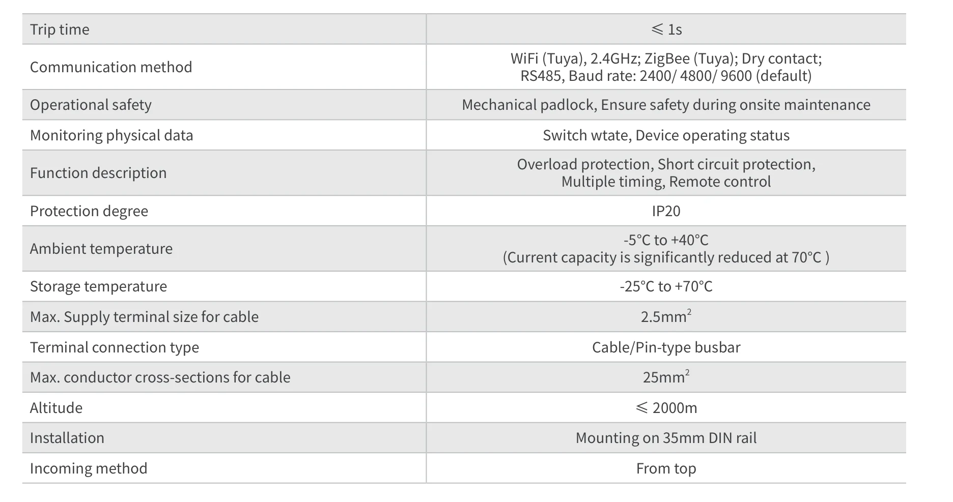
| Trip time | ≤ 1s |
| Communication method | WiFi (Tuya), 2.4GHz; ZigBee (Tuya); Dry contact; RS485, Baud rate: 2400/ 4800/ 9600 (default) |
| This product communication | WiFi (Tuya), 2.4GHz |
| Operational safety | Mechanical padlock, Ensure safety during onsite maintenance |
| Monitoring physical data | Switch state, Device operating status |
| Function description | Overload protection, Short circuit protection, Multiple timing, Remote control |
| Protection degree | IP20 |
| Ambient temperature | -5℃ to +40℃ (Current capacity is significantly reduced at 70℃) |
| Storage temperature | -25℃ to +70℃ |
| Max. Supply terminal size for cable | 2.5mm² |
| Terminal connection type | Cable/Pin-type busbar |
| Max. conductor cross-sections for cable | 25mm² |
| Altitude | ≤2000m |
| Installation | Mounting on 35mm DIN rail |
| Incoming method | From top |
Dimensions
Dimensions
Dimensions and Wiring Diagram
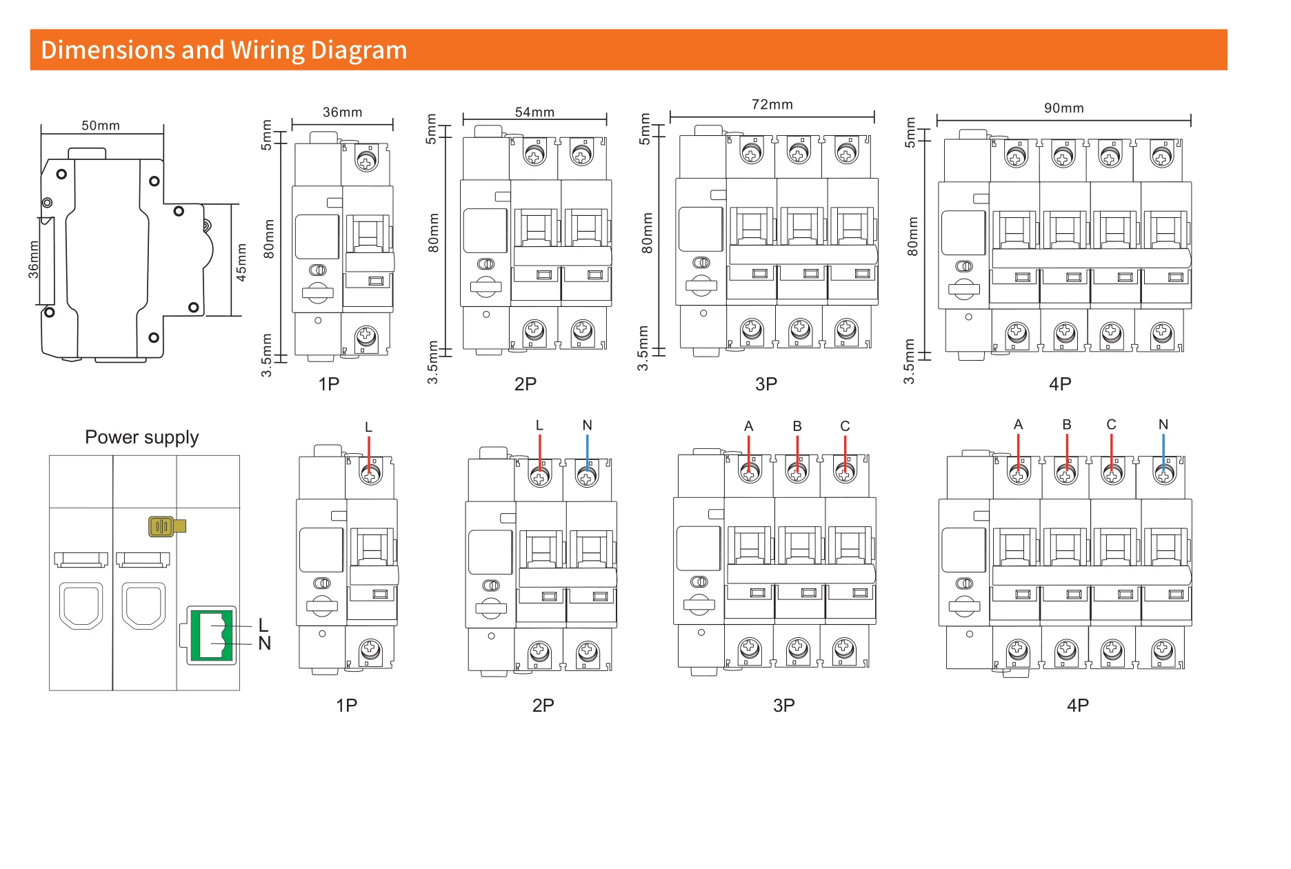
Dimension drawings cover side view and front views for 1P / 2P / 3P / 4P, including overall width values 36mm / 54mm / 72mm / 90mm, height-related marks such as 80mm / 45mm / 5mm / 3.5mm, and side depth marks such as 50mm / 36mm.
Wiring diagrams show power supply terminal (L / N) and pole wiring for 1P / 2P / 3P / 4P (L, N / A, B, C / A, B, C, N as applicable).